INSTALLATION
Continued
![]() WARNING: Never install the heater
WARNING: Never install the heater
•in a bedroom or bathroom
•in a recreational vehicle
•where curtains, furniture, clothing, or other flammable objects are less than 36 inches from the front, top, or sides of the heater
•as a fireplace insert
•in high traffic areas
•in windy or drafty areas
![]() CAUTION: If you install the heater in a home garage
CAUTION: If you install the heater in a home garage
•heater pilot and burner must be at least 18 inches above floor
•locate heater where moving vehicle will not hit it
![]() CAUTION: This heater cre- ates warm air currents. These currents move heat to wall sur- faces next to heater. Installing heater next to vinyl or cloth wall coverings or operating heater where impurities (such as, but not limited to, tobacco smoke, aromatic candles, cleaning flu- ids, oil or kerosene lamps, etc.) in the air exist, may discolor walls or cause odors.
CAUTION: This heater cre- ates warm air currents. These currents move heat to wall sur- faces next to heater. Installing heater next to vinyl or cloth wall coverings or operating heater where impurities (such as, but not limited to, tobacco smoke, aromatic candles, cleaning flu- ids, oil or kerosene lamps, etc.) in the air exist, may discolor walls or cause odors.
IMPORTANT:
For convenience and efficiency, install heater
•where there is easy access for operation, inspec- tion, and service
•in coldest part of room
An optional fan kit is available from your dealer. See Accessories, page 33. If planning to use fan, locate heater near an electrical outlet.
THERMOSTAT SENSING BULB
(Thermostat Models Only)
The thermostat sensing bulb has been placed be- low the heater.
1.Place clamp on thermostat sensing bulb as shown in Figure 5. Clamp is provided in hard- ware package.
2.Snap clamp into upper mounting hole as shown in Figure 5. Mounting hole is located on lower left edge on back of heater. Make sure the ther- mostat sensing bulb is pointing up.
Thermostat
![]() Sensing
Sensing
Bulb
![]() Clamp
Clamp
Figure 5 - Attaching Thermostat Sensing
Bulb
INSTALLING HEATER TO WALL
Mounting Bracket
Locate mounting bracket in heater carton. Remove mounting bracket from heater carton.
Figure 6 - Mounting Bracket
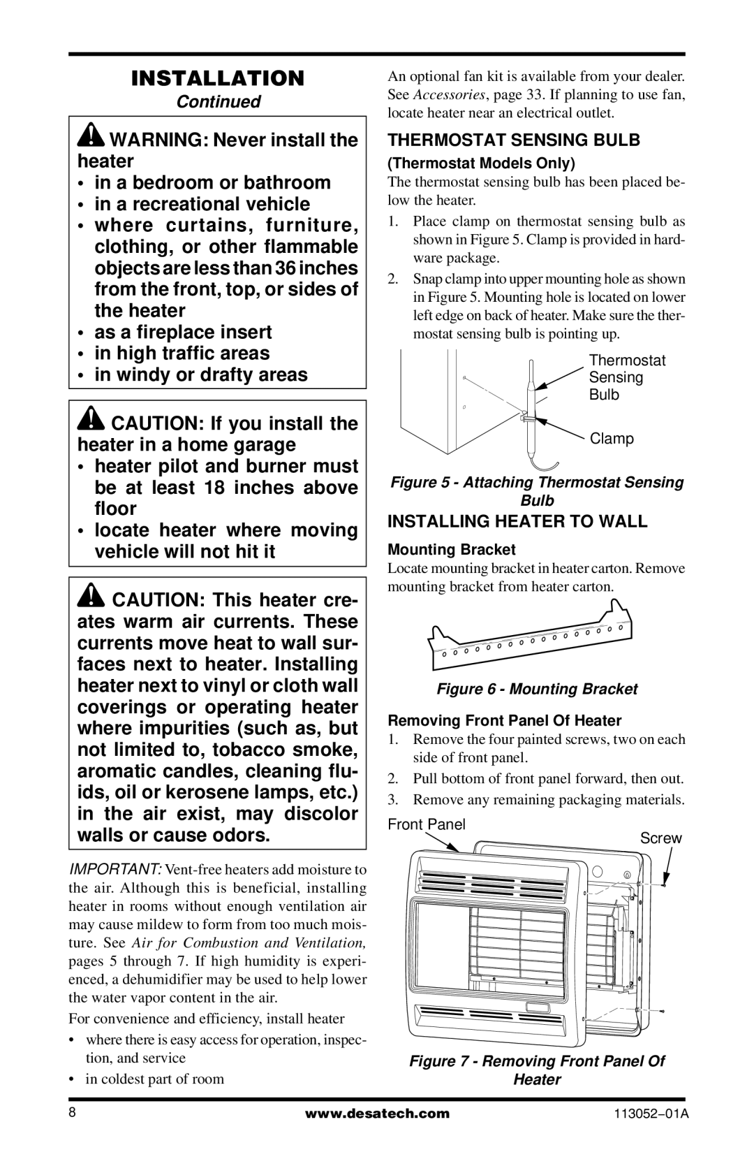
Removing Front Panel Of Heater
1.Remove the four painted screws, two on each side of front panel.
2.Pull bottom of front panel forward, then out.
3.Remove any remaining packaging materials.
Front Panel
Screw
Figure 7 - Removing Front Panel Of
Heater
8 | www.desatech.com |