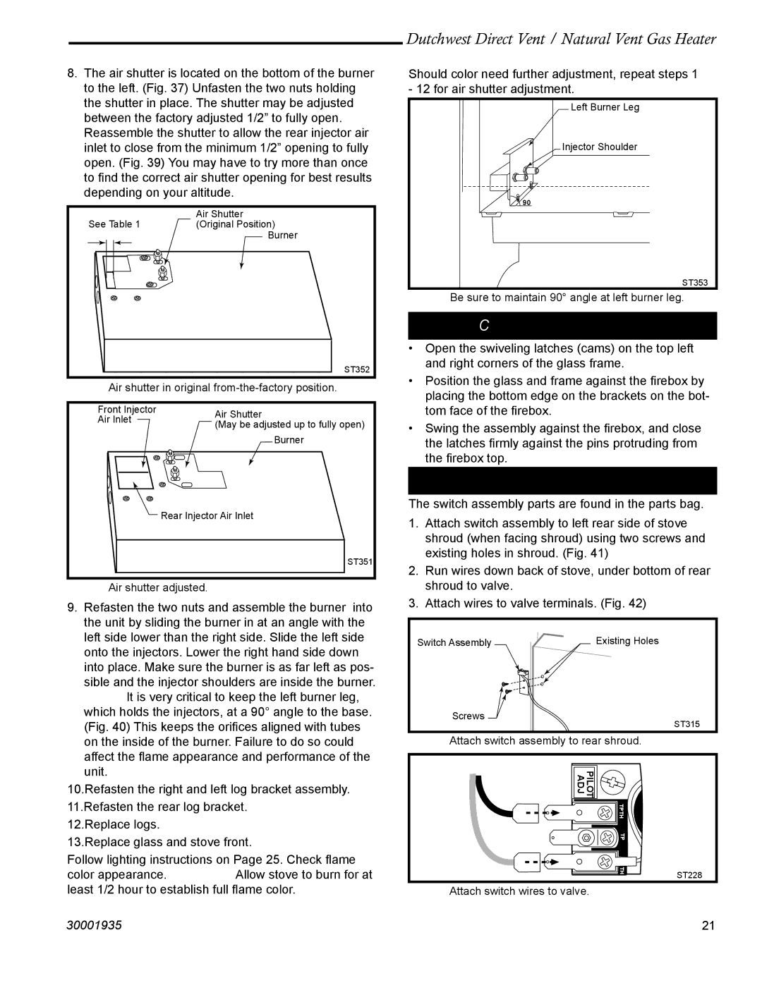
8.The air shutter is located on the bottom of the burner to the left. (Fig. 37) Unfasten the two nuts holding the shutter in place. The shutter may be adjusted between the factory adjusted 1/2” to fully open. Reassemble the shutter to allow the rear injector air inlet to close from the minimum 1/2” opening to fully open. (Fig. 39) You may have to try more than once to find the correct air shutter opening for best results depending on your altitude.


Air Shutter

See Table 1

(Original Position)


Burner


ST352

Fig. 38 Air shutter in original from-the-factory position.

Front Injector

Air Shutter

Air Inlet

(May be adjusted up to fully open)


Burner


Rear Injector Air Inlet


ST351

Fig. 39 Air shutter adjusted.

9.Refasten the two nuts and assemble the burner into the unit by sliding the burner in at an angle with the left side lower than the right side. Slide the left side onto the injectors. Lower the right hand side down into place. Make sure the burner is as far left as pos- sible and the injector shoulders are inside the burner. NOTE: It is very critical to keep the left burner leg, which holds the injectors, at a 90° angle to the base. (Fig. 40) This keeps the orifices aligned with tubes on the inside of the burner. Failure to do so could affect the flame appearance and performance of the unit.

10.Refasten the right and left log bracket assembly.

11.Refasten the rear log bracket.

12.Replace logs.

13.Replace glass and stove front.

Follow lighting instructions on Page 25. Check flame color appearance. NOTE: Allow stove to burn for at least 1/2 hour to establish full flame color.

Dutchwest Direct Vent / Natural Vent Gas Heater

Should color need further adjustment, repeat steps 1 - 12 for air shutter adjustment.

Left Burner Leg

Injector Shoulder

90°

ST353

Fig. 40 Be sure to maintain 90° angle at left burner leg.

Complete the Assembly

Open the swiveling latches (cams) on the top left and right corners of the glass frame.

Position the glass and frame against the firebox by placing the bottom edge on the brackets on the bot- tom face of the firebox.

Swing the assembly against the firebox, and close the latches firmly against the pins protruding from the firebox top.

Install ON/OFF Switch

The switch assembly parts are found in the parts bag.

1.Attach switch assembly to left rear side of stove shroud (when facing shroud) using two screws and existing holes in shroud. (Fig. 41)

2.Run wires down back of stove, under bottom of rear shroud to valve.

3.Attach wires to valve terminals. (Fig. 42)

Switch Assembly

Existing Holes

Screws

ST315

Fig. 41 Attach switch assembly to rear shroud.

PILOT


ADJ


TPTH


TP


TH

ST228


Fig. 42 Attach switch wires to valve.

30001935

21

Page 21
Image 21
Vermont Casting 2465, 2466 manual Complete the Assembly, Install ON/OFF Switch

2466, 2465 specifications

Vermont Casting's 2465 and 2466 stoves are renowned in the world of wood-burning appliances, celebrated for their blend of traditional craftsmanship, modern technology, and efficient features. These stoves bring warmth and aesthetic appeal to any home while providing an eco-friendly heating solution.

The Vermont Casting 2465 model stands out with its classic styling and robust construction, made from high-quality cast iron. Its design not only provides durability but also enhances heat retention, allowing for longer-lasting warmth in your space. Featuring a large viewing window, the 2465 allows you to enjoy the mesmerizing flames while also providing ample heat output, making it a focal point of any room.

Similarly, the Vermont Casting 2466 shares many characteristics with its counterpart but introduces slightly elevated features. One of the notable features of the 2466 is its increased heating capacity, suitable for larger homes or open-concept living spaces. Both models are equipped with a user-friendly air control system that optimizes airflow and combustion, ensuring that wood burns more efficiently and cleanly. This results in minimal smoke emissions and contributes to a lower environmental impact.

One of the standout technologies in both the 2465 and 2466 is the patented “Dual Air Control” system. This innovative design allows homeowners to easily adjust the airflow for more efficient burning, regardless of the type of wood used, enhancing combustion efficiency. Users can start with a higher airflow for a quick fire start and then throttle back once the wood is burning well, ensuring an effective and adjustable burn rate.

Additionally, both models come with an integrated ash pan located at the bottom, designed to simplify maintenance by making ash removal quick and easy. The stoves also feature a built-in heat shield that helps to increase the heating efficiency of the stove while reducing the clearance needed for safe installation.

Overall, the Vermont Casting 2465 and 2466 stoves represent an intersection of function and beauty. Their classic cast iron design paired with modern heating technologies makes them a perfect choice for those wishing to combine traditional aesthetics with efficiency and environmental responsibility in their home heating solutions. Whether you're heating a cozy cabin or a spacious family room, these stoves deliver exceptional performance and timeless appeal.