2466, 2465 specifications
Vermont Casting's 2465 and 2466 stoves are renowned in the world of wood-burning appliances, celebrated for their blend of traditional craftsmanship, modern technology, and efficient features. These stoves bring warmth and aesthetic appeal to any home while providing an eco-friendly heating solution.The Vermont Casting 2465 model stands out with its classic styling and robust construction, made from high-quality cast iron. Its design not only provides durability but also enhances heat retention, allowing for longer-lasting warmth in your space. Featuring a large viewing window, the 2465 allows you to enjoy the mesmerizing flames while also providing ample heat output, making it a focal point of any room.
Similarly, the Vermont Casting 2466 shares many characteristics with its counterpart but introduces slightly elevated features. One of the notable features of the 2466 is its increased heating capacity, suitable for larger homes or open-concept living spaces. Both models are equipped with a user-friendly air control system that optimizes airflow and combustion, ensuring that wood burns more efficiently and cleanly. This results in minimal smoke emissions and contributes to a lower environmental impact.
One of the standout technologies in both the 2465 and 2466 is the patented “Dual Air Control” system. This innovative design allows homeowners to easily adjust the airflow for more efficient burning, regardless of the type of wood used, enhancing combustion efficiency. Users can start with a higher airflow for a quick fire start and then throttle back once the wood is burning well, ensuring an effective and adjustable burn rate.
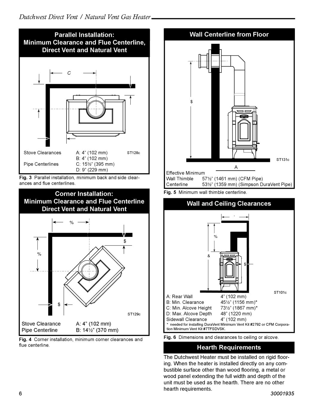
Additionally, both models come with an integrated ash pan located at the bottom, designed to simplify maintenance by making ash removal quick and easy. The stoves also feature a built-in heat shield that helps to increase the heating efficiency of the stove while reducing the clearance needed for safe installation.
Overall, the Vermont Casting 2465 and 2466 stoves represent an intersection of function and beauty. Their classic cast iron design paired with modern heating technologies makes them a perfect choice for those wishing to combine traditional aesthetics with efficiency and environmental responsibility in their home heating solutions. Whether you're heating a cozy cabin or a spacious family room, these stoves deliver exceptional performance and timeless appeal.

