Manuals
/
Vermont Casting
/
Household Appliance
/
Indoor Fireplace
Vermont Casting
D232
installation instructions
Options, FAN KIT - FK24, Remote Control
Models:
D232
1
26
28
28
Download
28 pages
37.45 Kb
21
22
23
24
25
26
27
28
Specifications
Flame Characteristics
Install
Parts list
Dimension
Symptom
Vent Pipe Assembly
Glass Cleaning
Remote Control
Freestanding Replacement Parts
Page 26
Image 26
Page 25
Page 27
Page 26
Image 26
Page 25
Page 27
Contents
Free-Standing Direct Vented Fireplaces
FOR YOUR SAFETY
FOR YOUR SAFETY
MODEL D232
TABLE OF CONTENTS
Crimped Ends Venting Components
LOCATING YOUR GAS FIREPLACE
INSTALLATION AND OPERATING INSTRUCTIONS
CLEARANCE TO COMBUSTIBLES
PLEASE REVIEW THE FOLLOWING
MODEL D232
A K C D EG F B
I J H
FIREPLACE DIMENSIONS
PREPARATION
GAS SPECIFICATIONS
GAS LINE INSTALLATION
D232 CERTIFIED TO
VALVE
INSTALLATION OF REMOTE SWITCH FOR RN/RP GAS VALVE
ON/OFF SWITCH OR
MILLIVOLT THERMOSTAT
F= clearance to outside comer see next page
GENERAL VENTING INFORMATION
Location of Vent Termination
G= clearance to inside comer see next page
Termination Clearances
D CC E
GENERAL INFORMATION ON ASSEMBLING THE VENT PIPES
CRIMPED END PIPES
TWIST LOCK PIPES
Screw Holes
Total
VERTICAL SIDEWALL INSTALLATIONS
VERTICAL SIDEWALL APPLICATIONS
270o
SIDEWALL VENTING GRAPH
Dimensions in Feet
TO USE THE VENT GRAPH
HORIZONTAL DIMENSION
STEP
VENT PIPE ASSEMBLY
BEAD OF SEALANT
STEP
STEP
BELOW GRADE INSTALLATIONS
STEP
STEP
VERTICAL THROUGH THE ROOF APPLICATIONS
run if the vertical exceeds
TO INSTALL VERTICAL VENTING
VERTICAL THRU THE ROOF APPLICATIONS
CRIMPED ENDS VENTING COMPONENTS
TWIST LOCK VENTING COMPONENTS
LOUVRE REMOVAL
OPERATING INSTRUCTIONS
GENERAL GLASS INFORMATION
TRIM REMOVAL
Clean glass after first two weeks of operation
GLASS CLEANING
INSTALLATION OF LOGS & BURNER LAVA ROCK MATERIAL
CLEANING PROCEDURE
MAINTENANCE
FLAME ADJUSTMENT RN/RP MODELS
FLAME CHARACTERISTICS
LIGHTING INSTRUCTIONS
FOR YOUR SAFETY READ BEFORE LIGHTING
LIGHTING AND OPERATING INSTRUCTIONS
TO TURN OFF GAS TO FIREPLACE
START
TROUBLE SHOOTING THE GAS CONTROL SYSTEM
HONEYWELL MILLIVOLT VALVE
CHECK
POSSIBLE CAUSES
SYMPTOM
SIT NOVA 820 MILLIVOLT VALVE
CORRECTIVE ACTION
DESCRIPTION
REPLACEMENT PARTS LIST
D232
#1 - COMPLETE LOG SET
FREESTANDING REPLACEMENT PARTS
D232
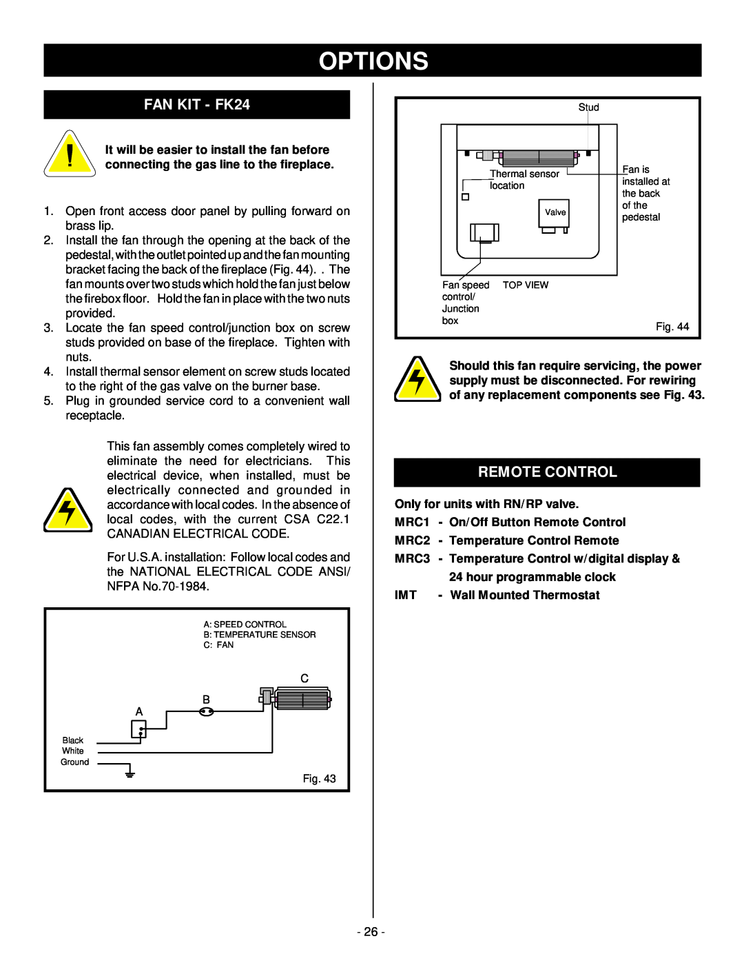
FAN KIT - FK24
REMOTE CONTROL
OPTIONS
Page
CFM Majestic, Inc
LIMITED WARRANTY & EXTENDED LIFE TIME PROTECTION
For Gas Appliance Products
Top
Page
Image
Contents