HEBTKP Trim Assembly
1)Reposition controls.
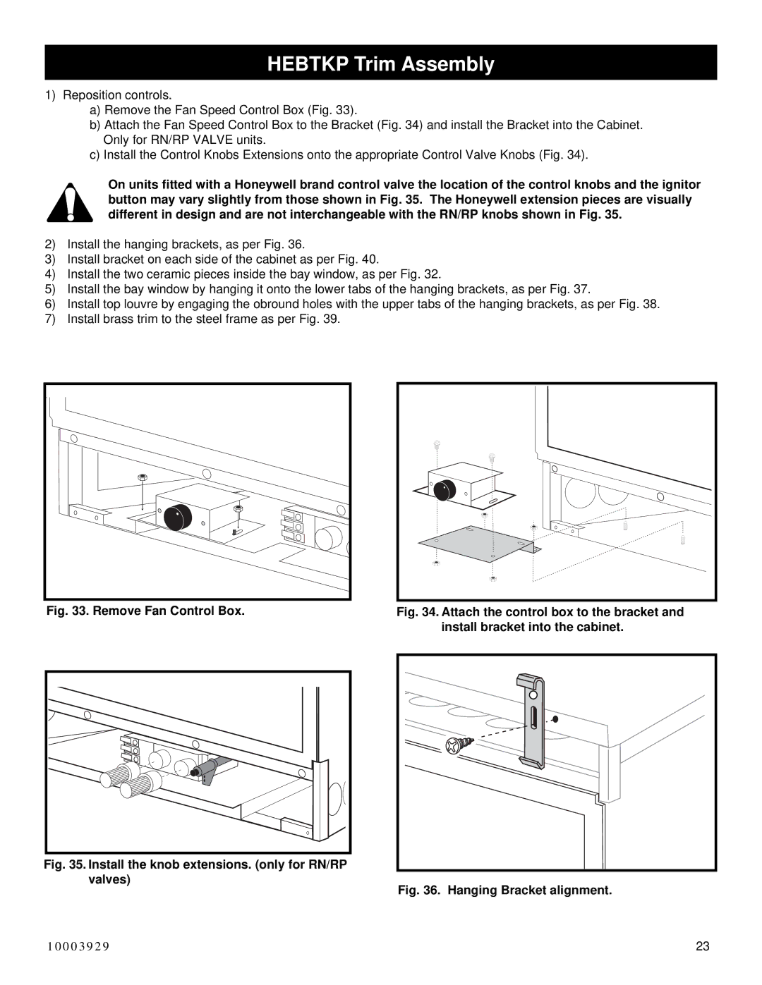
a)Remove the Fan Speed Control Box (Fig. 33).
b)Attach the Fan Speed Control Box to the Bracket (Fig. 34) and install the Bracket into the Cabinet. Only for RN/RP VALVE units.
c)Install the Control Knobs Extensions onto the appropriate Control Valve Knobs (Fig. 34).
On units fitted with a Honeywell brand control valve the location of the control knobs and the ignitor button may vary slightly from those shown in Fig. 35. The Honeywell extension pieces are visually different in design and are not interchangeable with the RN/RP knobs shown in Fig. 35.
2)Install the hanging brackets, as per Fig. 36.
3)Install bracket on each side of the cabinet as per Fig. 40.
4)Install the two ceramic pieces inside the bay window, as per Fig. 32.
5)Install the bay window by hanging it onto the lower tabs of the hanging brackets, as per Fig. 37.
6)Install top louvre by engaging the obround holes with the upper tabs of the hanging brackets, as per Fig. 38.
7)Install brass trim to the steel frame as per Fig. 39.
Fig. 33. Remove Fan Control Box.
Fig. 34. Attach the control box to the bracket and install bracket into the cabinet.
Fig. 35. Install the knob extensions. (only for RN/RP
valves)
Fig. 36. Hanging Bracket alignment.
10003929 | 23 |