INSTALLATION OF TRIM SWITCH
FOR RP GAS VALVES
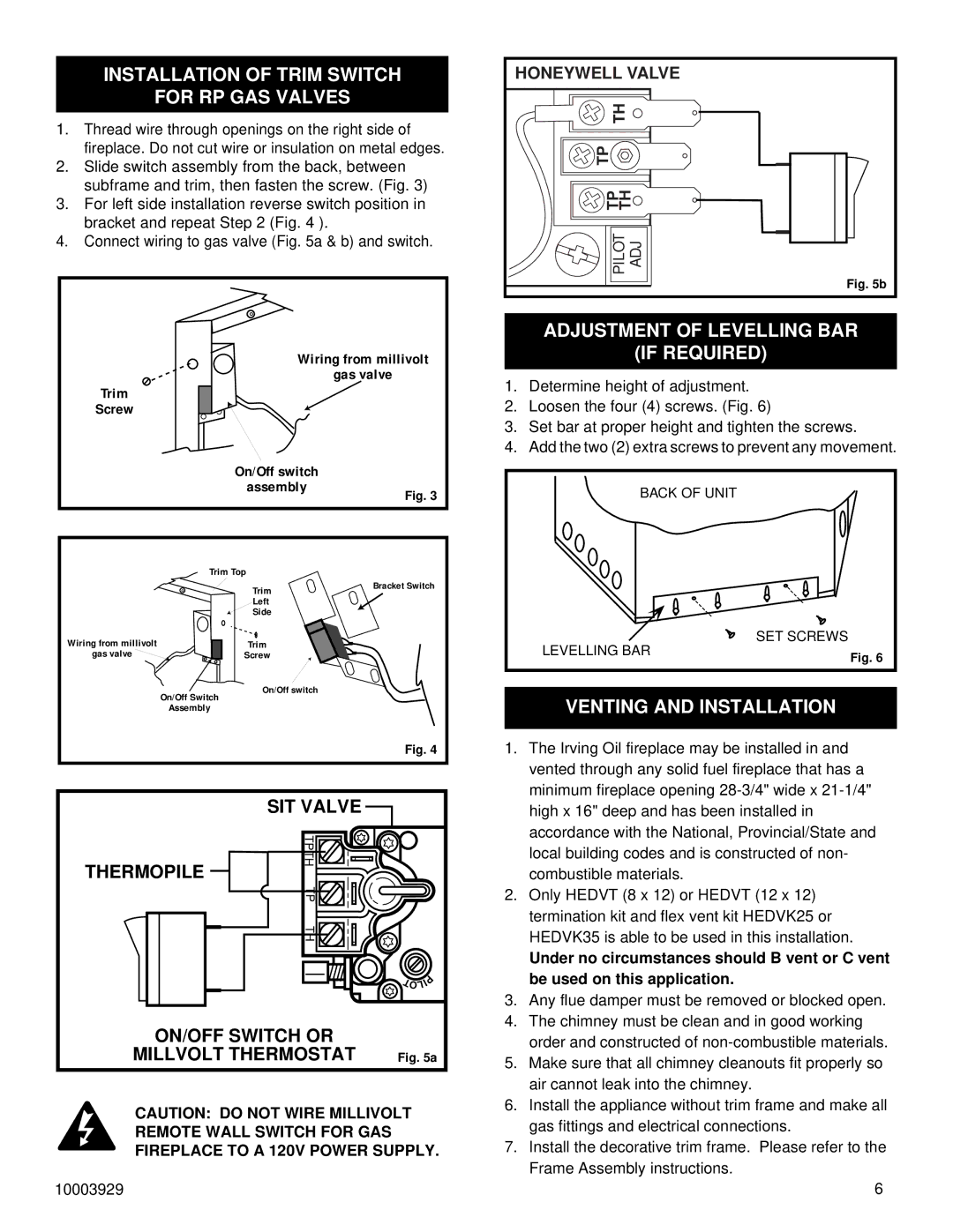
1.Thread wire through openings on the right side of fireplace. Do not cut wire or insulation on metal edges.
2.Slide switch assembly from the back, between subframe and trim, then fasten the screw. (Fig. 3)
3.For left side installation reverse switch position in bracket and repeat Step 2 (Fig. 4 ).
4.Connect wiring to gas valve (Fig. 5a & b) and switch.
Wiring from millivolt
gas valve
Trim
Screw
On/Off switch
HONEYWELL VALVE | |
TH |
|
TP |
|
TP TH | |
PILOT | ADJ |
| Fig. 5b |
ADJUSTMENT OF LEVELLING BAR
(IF REQUIRED)
1.Determine height of adjustment.
2.Loosen the four (4) screws. (Fig. 6)
3.Set bar at proper height and tighten the screws.
4.Add the two (2) extra screws to prevent any movement.
assembly
Trim Top
Fig. 3
BACK OF UNIT |
Wiring from millivolt gas valve ![]()
On/Off Switch
Assembly
Trim | Bracket Switch |
Left |
|
Side |
|
Trim
Screw
On/Off switch
| ||
|
| |
LEVELLING BAR |
| SET SCREWS |
| Fig. 6 | |
|
|
VENTING AND INSTALLATION
Fig. 4
| SIT VALVE |
|
|
|
THERMOPILE | TPTH |
|
|
|
|
|
|
| |
| TP |
|
|
|
| TH |
|
|
|
|
|
|
| P |
|
|
| I | |
|
| T L |
| |
|
| O |
|
|
ON/OFF SWITCH OR |
|
|
| |
MILLVOLT THERMOSTAT | Fig. 5a | |||
CAUTION: DO NOT WIRE MILLIVOLT REMOTE WALL SWITCH FOR GAS FIREPLACE TO A 120V POWER SUPPLY.
10003929
1.The Irving Oil fireplace may be installed in and vented through any solid fuel fireplace that has a minimum fireplace opening
2.Only HEDVT (8 x 12) or HEDVT (12 x 12) termination kit and flex vent kit HEDVK25 or HEDVK35 is able to be used in this installation.
Under no circumstances should B vent or C vent be used on this application.
3.Any flue damper must be removed or blocked open.
4.The chimney must be clean and in good working order and constructed of
5.Make sure that all chimney cleanouts fit properly so air cannot leak into the chimney.
6.Install the appliance without trim frame and make all gas fittings and electrical connections.
7.Install the decorative trim frame. Please refer to the Frame Assembly instructions.
6