LHECDV20, LHERDV30, LHECDV30, LHERDV20 specifications
Vermont Castings is renowned for its commitment to offering high-quality, efficient, and aesthetically pleasing gas fireplaces. Amongst its esteemed lineup, the LHECDV20, LHERDV20, LHECDV30, and LHERDV30 stand out for their exceptional features and innovative technologies that cater to a wide range of consumer needs.The LHECDV20 and LHECDV30 models are designed for those seeking a compact yet powerful heating solution. Both units embody Vermont Castings' signature cast-iron construction, which not only enhances durability but also provides excellent heat retention. The LHECDV20 has a smaller footprint ideal for smaller spaces, while the LHECDV30 offers a broader heating range, making it suitable for larger areas. Each model features a stunning view of the flames, achieved through large glass doors that create a warm and inviting atmosphere.
Both models utilize advanced burner technology that maximizes efficiency and minimizes emissions. The unique design ensures uniform heat distribution, which is complemented by an adjustable flame height feature. This allows you to customize the ambiance according to your preference, whether you desire a roaring fire or a gentle warmth.
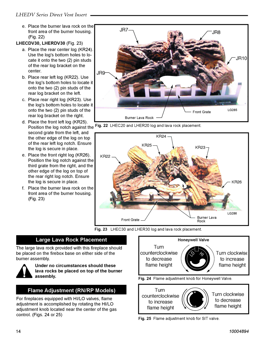
The LHERDV20 and LHERDV30, on the other hand, come equipped with a realistic log set and more intricate burner systems. These units replicate the organic look of a traditional wood fire, ensuring that aesthetics do not compromise performance. The radiant heat technology in these models ensures the warmth is felt throughout the room while maintaining an eco-friendly approach to heating.
Safety features are a paramount consideration in the design of all Vermont Castings models. Each unit is equipped with an advanced safety pilot system that provides peace of mind for homeowners. Additionally, the easy-to-use remote control allows users to operate the fireplaces from the comfort of their chair, making heating your space convenient and hassle-free.
Installation is made easy with top-venting options available for each model, allowing flexibility in settings. Vermont Castings also offers an array of customizable options, enabling you to personalize your fireplace to match your home’s decor.
In summary, the Vermont Castings LHECDV20, LHERDV20, LHECDV30, and LHERDV30 gas fireplaces offer a harmonious blend of efficiency, beauty, and technology. Their commitment to quality ensures that you not only enjoy the warmth but also the elegance that these fireplaces bring to your living environment. Whether you have a cozy cabin or a spacious home, these models offer a solution to meet your heating needs while enhancing the aesthetic appeal of your space.

