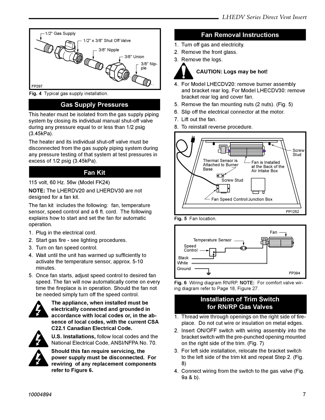
1/2" Gas Supply


1/2" x 3/8" Shut Off Valve


3/8" Nipple


3/8" Union


3/8" Nip-


ple

FP297


Fig. 4

Typical gas supply installation.

Gas Supply Pressures

This heater must be isolated from the gas supply piping system by closing its individual manual shut-off valve during any pressure equal to or less than 1/2 psig (3.45kPa).

The heater and its individual shut-off valve must be disconnected from the gas supply piping system during any pressure testing of that system at test pressures in excess of 1/2 psig (3.45kPa).

Fan Kit

115 volt, 60 Hz. 56w (Model FK24)

NOTE: The LHERDV20 and LHERDV30 are not designed for a fan kit.

The fan kit includes the following: fan, temperature sensor, speed control and a 6 ft. cord. The following explains how to start and set the fan for automatic operation.

1.Plug in the electrical cord.

2.Start gas fire - see lighting procedures.

3.Turn on fan speed control.

4.Wait until the unit has warmed up sufficiently to activate the temperature sensor, approx. 5-10 minutes.

5.Once fan starts, adjust speed control to desired fan speed. The fan will now automatically come on every time the fireplace is in operation. Should the fan not be needed simply turn off the speed control.

The appliance, when installed must be electrically connected and grounded in accordance with local codes or, in the ab- sence of local codes, with the current CSA C22.1 Canadian Electrical Code.

U.S. Installations, follow local codes and the National Electrical Code, ANSI/NFPA No. 70.

Should this fan require servicing, the power supply must be disconnected. For rewiring of any replacement components refer to Figure 6.

LHEDV Series Direct Vent Insert

Fan Removal Instructions

1.Turn off gas and electricity.

2.Remove the front glass.

3.Remove the logs.

CAUTION: Logs may be hot!

4.For Model LHECDV20: remove burner assembly

and bracket rear log. For Model LHECDV30: remove bracket rear log and cover fan.

5.Remove the fan mounting nuts (2 nuts). (Fig. 5)

6.Slip off the electrical connector at the motor.

7.Lift out the fan.

8.To reinstall reverse procedure.

Screw

Stud

Thermal Sensor is

Fan is Installed

Attached to Burner

at the Back of the

Base

Air Intake Box


Screw Stud


Fan Speed Control/Junction Box


FP1252

Fig. 5

Fan location.


Fan


Temperature Sensor

Speed

Control

Black


White


Ground


FP394

Fig. 6 Wiring diagram RN/RP. NOTE: For comfort valve wir- ing diagram refer to Page 18, Figure 27.

Installation of Trim Switch

for RN/RP Gas Valves

1.Thread wire through openings on the right side of fire- place. Do not cut wire or insulation on metal edges.

2.Insert ON/OFF switch with wiring assembly into the bracket switch with the pre-punched opening mounted on the right side of the trim. (Fig. 7)

3.For left side installation, relocate the bracket switch to the left side of the trim kit and repeat Step 2. (Fig. 8)

4.Connect wiring from the switch to the gas valve (Fig. 9a & b).

10004894

7

Page 7
Image 7
Vermont Casting LHECDV20, LHERDV20, LHECDV30, LHERDV30 manual Gas Supply Pressures, Fan Kit, Fan Removal Instructions

LHECDV20, LHERDV30, LHECDV30, LHERDV20 specifications

Vermont Castings is renowned for its commitment to offering high-quality, efficient, and aesthetically pleasing gas fireplaces. Amongst its esteemed lineup, the LHECDV20, LHERDV20, LHECDV30, and LHERDV30 stand out for their exceptional features and innovative technologies that cater to a wide range of consumer needs.

The LHECDV20 and LHECDV30 models are designed for those seeking a compact yet powerful heating solution. Both units embody Vermont Castings' signature cast-iron construction, which not only enhances durability but also provides excellent heat retention. The LHECDV20 has a smaller footprint ideal for smaller spaces, while the LHECDV30 offers a broader heating range, making it suitable for larger areas. Each model features a stunning view of the flames, achieved through large glass doors that create a warm and inviting atmosphere.

Both models utilize advanced burner technology that maximizes efficiency and minimizes emissions. The unique design ensures uniform heat distribution, which is complemented by an adjustable flame height feature. This allows you to customize the ambiance according to your preference, whether you desire a roaring fire or a gentle warmth.

The LHERDV20 and LHERDV30, on the other hand, come equipped with a realistic log set and more intricate burner systems. These units replicate the organic look of a traditional wood fire, ensuring that aesthetics do not compromise performance. The radiant heat technology in these models ensures the warmth is felt throughout the room while maintaining an eco-friendly approach to heating.

Safety features are a paramount consideration in the design of all Vermont Castings models. Each unit is equipped with an advanced safety pilot system that provides peace of mind for homeowners. Additionally, the easy-to-use remote control allows users to operate the fireplaces from the comfort of their chair, making heating your space convenient and hassle-free.

Installation is made easy with top-venting options available for each model, allowing flexibility in settings. Vermont Castings also offers an array of customizable options, enabling you to personalize your fireplace to match your home’s decor.

In summary, the Vermont Castings LHECDV20, LHERDV20, LHECDV30, and LHERDV30 gas fireplaces offer a harmonious blend of efficiency, beauty, and technology. Their commitment to quality ensures that you not only enjoy the warmth but also the elegance that these fireplaces bring to your living environment. Whether you have a cozy cabin or a spacious home, these models offer a solution to meet your heating needs while enhancing the aesthetic appeal of your space.