Stardance Direct Vent/Natural Vent Gas Heater
Installation Requirements
The installation must conform with local codes or, in |
|
|
|
|
|
| |
the absence of local codes, with the National Fuel Gas |
|
|
|
Code, ANSI Z223.1/NFPA 54 - latest edition. (EXCEP- |
|
|
|
TION: Do not derate this appliance for altitude. Main- |
| A |
|
tain the manifold pressure at 3.5 inches w.c. for Natural |
| D | |
Gas, and 10 inches w.c. for Propane). |
| B |
|
In Canada, installation must be in accordance with the |
| C |
|
current CSA |
|
|
|
codes. |
| E |
|
The installation should be done by a qualified ser- |
|
|
|
vice person who is familiar with the building codes |
|
|
|
and installation techniques appropriate for your |
|
| ST207 |
area to accomplish a safe and effective installation. |
|
| |
|
|
| |
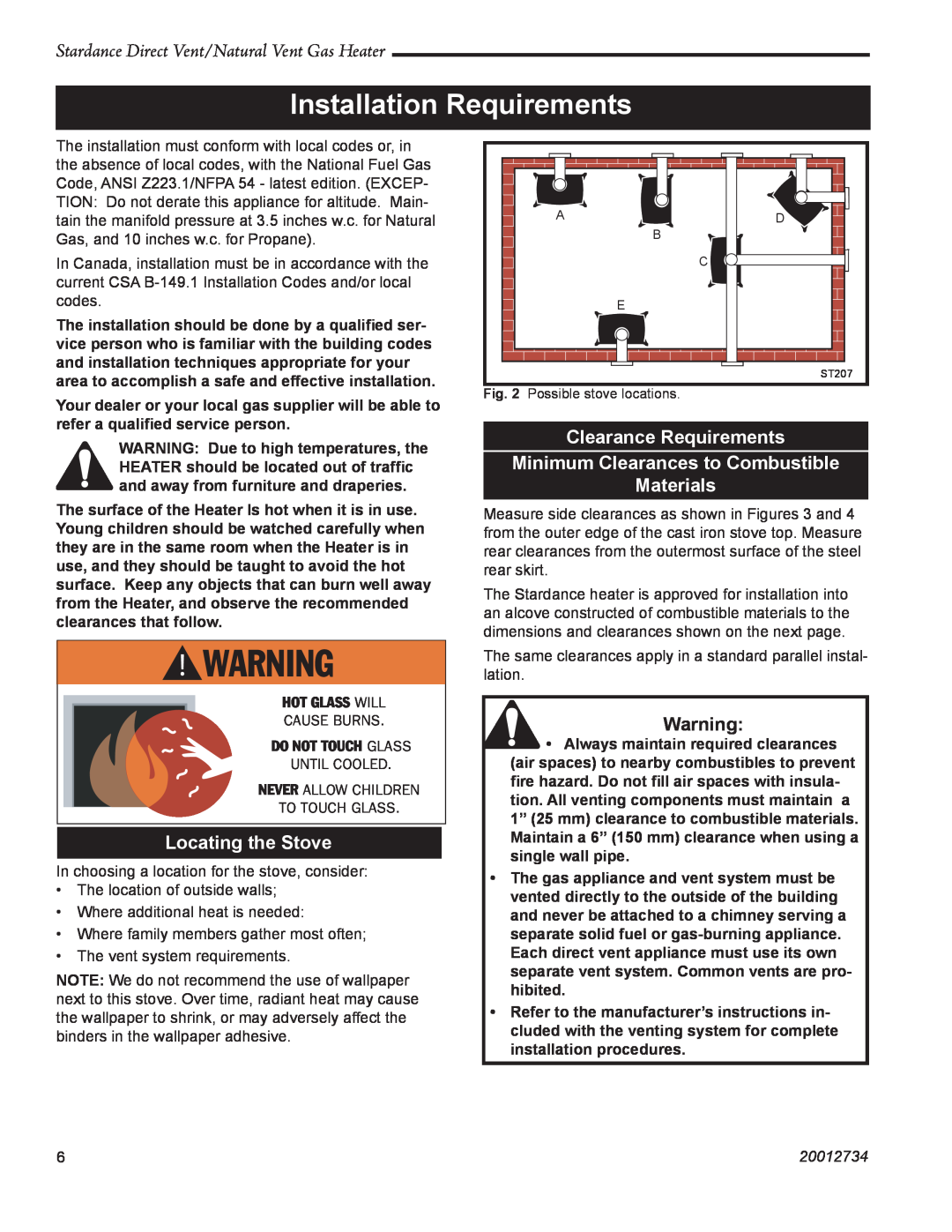
| Fig. 2 Possible stove locations. |
| |
Your dealer or your local gas supplier will be able to |
|
| |
|
|
| |
refer a qualified service person. |
|
|
|
| Clearance Requirements | ||
WARNING: Due to high temperatures, the |
| ||
| Minimum Clearances to Combustible | ||
HEATER should be located out of traffic |
| ||
and away from furniture and draperies. |
| Materials |
|
The surface of the Heater Is hot when it is in use. |
|
| |
| Measure side clearances as shown in Figures 3 and 4 | ||
Young children should be watched carefully when |
| from the outer edge of the cast iron stove top. Measure | |
they are in the same room when the Heater is in |
| rear clearances from the outermost surface of the steel | |
use, and they should be taught to avoid the hot |
| rear skirt. |
|
surface. Keep any objects that can burn well away |
| The Stardance heater is approved for installation into | |
from the Heater, and observe the recommended |
| ||
| an alcove constructed of combustible materials to the | ||
clearances that follow. |
| ||
| dimensions and clearances shown on the next page. | ||
� ������� |
| ||
| lation. |
| |
|
| The same clearances apply in a standard parallel instal- | |
�������������� |
|
|
|
|
|
| |
������������ |
| Warning: |
|
������������������ |
| • Always maintain required clearances | |
������������� |
| (air spaces) to nearby combustibles to prevent | |
�������������������� |
| fire hazard. Do not fill air spaces with insula- | |
| tion. All venting components must maintain a | ||
��������������� |
| ||
| 1” (25 mm) clearance to combustible materials. | ||
|
| ||
Locating the Stove |
| Maintain a 6” (150 mm) clearance when using a | |
|
| single wall pipe. |
|
In choosing a location for the stove, consider: |
|
| |
| • The gas appliance and vent system must be | ||
• The location of outside walls; |
| ||
| vented directly to the outside of the building | ||
• Where additional heat is needed: |
| ||
| and never be attached to a chimney serving a | ||
• Where family members gather most often; |
| separate solid fuel or | |
• The vent system requirements. |
| Each direct vent appliance must use its own | |
NOTE: We do not recommend the use of wallpaper |
| separate vent system. Common vents are pro- | |
| hibited. |
| |
next to this stove. Over time, radiant heat may cause |
|
| |
| • Refer to the manufacturer’s instructions in- | ||
the wallpaper to shrink, or may adversely affect the |
| ||
| cluded with the venting system for complete | ||
binders in the wallpaper adhesive. |
| ||
| installation procedures. |
| |
|
|
| |
|
|
|
|
6 | 20012734 |