Stardance Natural Vent Gas Heater
Installation
Unpack the Stove
The Stardance is shipped fully assembled on its back. Unpack the stove and carefully set it upright.
CAUTION
Porcelain enamelled surfaces are fragile. Handle porcelain enamelled castings tenderly. Familiarize yourself with the assembly steps before you begin and proceed with deliberation and care. If possible, have assistance available.
Place enamelled castings on a soft, cushioned sur- face until you are ready to assemble.
Avoid contact between the castings and other hard surfaces or objects.
Install the Optional Fan
WARNING
This appliance is equipped with a
If you are installing the optional convection Fan Kit #2767 (FK26), continue here. If you are not installing a fan kit, proceed to Venting System Assembly.
1.The fan kit includes a blower assembly and a rheo- stat assembly, connected by a cable. The blower as- sembly mounts to the bottom rear of the stove, and the rheostat mounts to the left side of the valve. The assembly includes a ‘snapstat’ which automatically turns the fan ON (or OFF) above (or below) approxi- mately 109°F. The rheostat also provides a range of fan speed settings from Off (which overrides the snapstat function) to High. Unpack and inspect the blower assembly. Confirm that the fan spins freely.
2.Remove the rear shroud by loosening the two (2) bolts at the bottom left and right side of the shroud. Slide shroud straight up, rotate the bottom out and away from stove and pull shroud out.
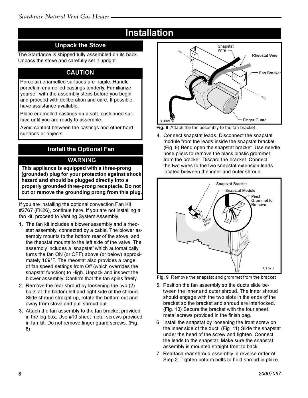
3.Attach the fan assembly to the fan bracket provided in the log box. Use #10 sheet metal screws provided in fan kit. Do not remove finger guard screws. (Fig.
8)
Snapstat
Wire
![]() Rheostat Wire
Rheostat Wire
![]() Fan Bracket
Fan Bracket
ST669 | Finger Guard |
Fig. 8 Attach the fan assembly to the fan bracket.
4.Connect snapstat leads. Disconnect the snapstat module from the leads inside the snapstat bracket. (Fig. 9) Bend open the snapstat bracket. Use needle nose pliers to remove the black plastic grommet from the bracket. Discard the bracket. Connect
the two wires to the two snapstat extension leads located between the inner and outer shroud.
Snapstat Bracket
Snapstat Module
Pinch
Grommet to
Remove
ST670
Fig. 9 Remove the snapstat and grommet from the bracket
5.Position the fan assembly so the ducts slide be- tween the inner and outer shroud. The inner shroud should engage with the two slots in the ends of the bracket so the bracket and shroud are interlocked. (Fig. 10) Secure the bracket with the four sheet metal screws provided in the finish bag.
6.Install the snapstat by loosening the front screw on the inner side of the duct. (Fig. 11) Slide the snapstat under the head of the screw and tighten. Connect the leads to the snapstat. Make sure the snapstat assembly is mounted straight front to back.
7.Reattach rear shroud assembly in reverse order of Step 2. Tighten bottom bolts to hold shroud in place.
88 | 20007067 |