VIVOTEK
DI/DO Diagram
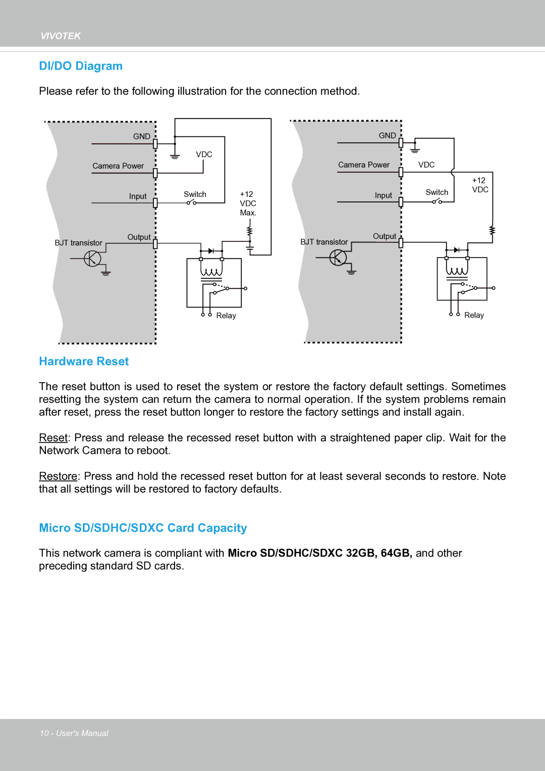
Please refer to the following illustration for the connection method.
GND
Camera Power
Input
BJT transistor |
|
| Output | |||||
|
|
| ||||||
|
|
|
|
|
|
|
|
|
|
|
|
|
|
|
|
|
|
|
|
|
|
|
|
|
|
|
|
|
|
|
|
|
|
|
|
|
|
|
|
|
|
|
|
|
VDC |
|
Switch | +12 |
| VDC |
| Max. |
Relay |
GND
Camera Power
Input
BJT transistor |
|
| Output | |||||
|
|
| ||||||
|
|
|
|
|
|
|
|
|
|
|
|
|
|
|
|
|
|
|
|
|
|
|
|
|
|
|
|
|
|
|
|
|
|
|
|
VDC
+12
Switch VDC
Relay |
Hardware Reset
The reset button is used to reset the system or restore the factory default settings. Sometimes resetting the system can return the camera to normal operation. If the system problems remain after reset, press the reset button longer to restore the factory settings and install again.
Reset: Press and release the recessed reset button with a straightened paper clip. Wait for the Network Camera to reboot.
Restore: Press and hold the recessed reset button for at least several seconds to restore. Note that all settings will be restored to factory defaults.
Micro SD/SDHC/SDXC Card Capacity
This network camera is compliant with Micro SD/SDHC/SDXC 32GB, 64GB, and other preceding standard SD cards.
10 - User's Manual