Installation Instructions

DIRECT CONNECT APPLICATIONS

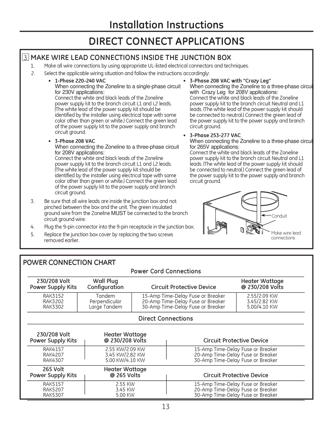
MAKE WIRE LEAD CONNECTIONS INSIDE THE JUNCTION BOX

1.Make all wire connections by using appropriate UL-listed electrical connectors and techniques.

2.Select the applicable wiring situation and follow the instructions accordingly:


1-Phase 220-240 VAC

3-Phase 208 VAC with “Crazy Leg”


When connecting the Zoneline to a single-phase circuit


When connecting the Zoneline to a three-phase circuit


for 230V applications:


with “Crazy Leg” for 208V applications:


Connect the white and black leads of the Zoneline


Connect the white and black leads of the Zoneline


power supply kit to the branch circuit L1 and L2 leads.


power supply kit to the branch circuit Neutral and L1


(The white lead of the power supply kit should be


leads. (The white lead of the power supply kit should


identified by the installer using electrical tape with some


be connected to neutral.) Connect the green lead of


color other than green or white.) Connect the green lead


the power supply kit to the power supply and branch


of the power supply kit to the power supply and branch


circuit ground.


circuit ground.

3-Phase 253-277 VAC


3-Phase 208 VAC


When connecting the Zoneline to a three-phase circuit


When connecting the Zoneline to a three-phase circuit


for 265V applications:


for 208V applications:


Connect the white and black leads of the Zoneline


Connect the white and black leads of the Zoneline


power supply kit to the branch circuit Neutral and L1


power supply kit to the branch circuit L1 and L2 leads.


leads. (The white lead of the power supply kit should


(The white lead of the power supply kit should be


be connected to neutral.) Connect the green lead of


identified by the installer using electrical tape with some


the power supply kit to the power supply and branch


color other than green or white.) Connect the green lead


circuit ground.


of the power supply kit to the power supply and branch


circuit ground.


3.

Be sure that all wire leads are inside the junction box and not


pinched between the box and the unit. The green insulated


ground wire from the Zoneline MUST be connected to the branch


Conduit


circuit ground wire.


4.

Plug the 9-pin connector into the 9-pin receptacle in the junction box.

5.

Replace the junction box cover by replacing the two screws


Make wire lead


removed earlier.


connections


POWER CONNECTION CHART

Power Cord Connections

230/208 Volt

Wall Plug


Heater Wattage

Power Supply Kits

Configuration

Circuit Protective Device

@ 230/208 Volts

RAK3152

Tandem

15-Amp Time-Delay Fuse or Breaker

2.55/2.09 KW

RAK3202

Perpendicular

20-Amp Time-Delay Fuse or Breaker

3.45/2.82 KW

RAK3302

Large Tandem

30-Amp Time-Delay Fuse or Breaker

5.00/4.10 KW

Direct Connections

230/208 Volt

Heater Wattage


Power Supply Kits

@ 230/208 Volts

Circuit Protective Device

RAK4157

2.55 KW/2.09 KW

15-Amp Time-Delay Fuse or Breaker

RAK4207

3.45 KW/2.82 KW

20-Amp Time-Delay Fuse or Breaker

RAK4307

5.00 KW/4.10 KW

30-Amp Time-Delay Fuse or Breaker

265 Volt

Heater Wattage


Power Supply Kits

@ 265 Volts

Circuit Protective Device

RAK5157

2.55 KW

15-Amp Time-Delay Fuse or Breaker

RAK5207

3.45 KW

20-Amp Time-Delay Fuse or Breaker

RAK5307

5.00 KW

30-Amp Time-Delay Fuse or Breaker

13

Page 13
Image 13
GE 8500 Series installation instructions Make Wire Lead Connections Inside the Junction BOX, Power Connection Chart

8500 Series specifications

The GE 8500 Series represents a remarkable advancement in the realm of industrial gas turbines, combining efficiency, reliability, and flexibility. Designed to meet the demands of current energy markets, this series of turbines is engineered for both baseload and peak-load applications, making it an ideal choice for operators seeking to optimize their energy production.

One of the standout features of the GE 8500 Series is its exceptional thermal efficiency. With a capability of achieving efficiency levels exceeding 60%, these turbines significantly reduce fuel consumption and lower greenhouse gas emissions. This feature not only makes them environmentally friendly but also helps operators reduce operational costs in the long run, positioning them favorably in a competitive energy landscape.

The GE 8500 Series incorporates advanced airfoil technologies that enhance performance. Featuring an innovative blade design, these turbines are capable of operating efficiently across a wide range of operating conditions. The materials used in the construction of the blades are engineered for durability, allowing them to withstand the harsh environments often encountered in power generation. This greatly extends the service life of the turbine and reduces downtime for maintenance.

Another important aspect of the GE 8500 Series is its adaptability. These turbines can utilize various fuels, including natural gas, hydrogen, and biofuels, offering flexibility to operators in terms of resource management. This feature allows utilities to adjust to changing fuel availability and price fluctuations, ensuring consistent energy generation.

The control and monitoring systems integrated into the GE 8500 Series are state-of-the-art, featuring advanced digital control technologies that provide real-time performance data. This allows operators to make informed decisions regarding maintenance and operational adjustments, ultimately enhancing the overall reliability of the power generation system.

In addition to these advancements, the GE 8500 Series is designed with a focus on reduced emissions without compromising performance. The turbines incorporate advanced combustion technologies that facilitate ultra-low emissions, aligning with the global movement toward cleaner energy solutions.

In conclusion, the GE 8500 Series is an exceptional line of gas turbines that combines high efficiency, flexibility, and low emissions. With advanced technologies and robust features, these turbines are positioned to meet the evolving needs of the energy sector while supporting the transition to a more sustainable future.