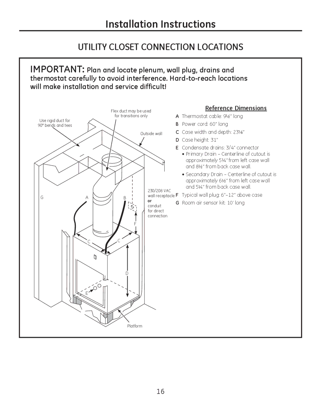
8500 Series specifications
The GE 8500 Series represents a remarkable advancement in the realm of industrial gas turbines, combining efficiency, reliability, and flexibility. Designed to meet the demands of current energy markets, this series of turbines is engineered for both baseload and peak-load applications, making it an ideal choice for operators seeking to optimize their energy production.One of the standout features of the GE 8500 Series is its exceptional thermal efficiency. With a capability of achieving efficiency levels exceeding 60%, these turbines significantly reduce fuel consumption and lower greenhouse gas emissions. This feature not only makes them environmentally friendly but also helps operators reduce operational costs in the long run, positioning them favorably in a competitive energy landscape.
The GE 8500 Series incorporates advanced airfoil technologies that enhance performance. Featuring an innovative blade design, these turbines are capable of operating efficiently across a wide range of operating conditions. The materials used in the construction of the blades are engineered for durability, allowing them to withstand the harsh environments often encountered in power generation. This greatly extends the service life of the turbine and reduces downtime for maintenance.
Another important aspect of the GE 8500 Series is its adaptability. These turbines can utilize various fuels, including natural gas, hydrogen, and biofuels, offering flexibility to operators in terms of resource management. This feature allows utilities to adjust to changing fuel availability and price fluctuations, ensuring consistent energy generation.
The control and monitoring systems integrated into the GE 8500 Series are state-of-the-art, featuring advanced digital control technologies that provide real-time performance data. This allows operators to make informed decisions regarding maintenance and operational adjustments, ultimately enhancing the overall reliability of the power generation system.
In addition to these advancements, the GE 8500 Series is designed with a focus on reduced emissions without compromising performance. The turbines incorporate advanced combustion technologies that facilitate ultra-low emissions, aligning with the global movement toward cleaner energy solutions.
In conclusion, the GE 8500 Series is an exceptional line of gas turbines that combines high efficiency, flexibility, and low emissions. With advanced technologies and robust features, these turbines are positioned to meet the evolving needs of the energy sector while supporting the transition to a more sustainable future.

