VIVOTEK
General I/O Terminal Block
This Network Camera provides two digital input pins that can be connected to external sensor devices. The pin definitions are described below.
![]()
![]() GND DI
GND DI ![]()
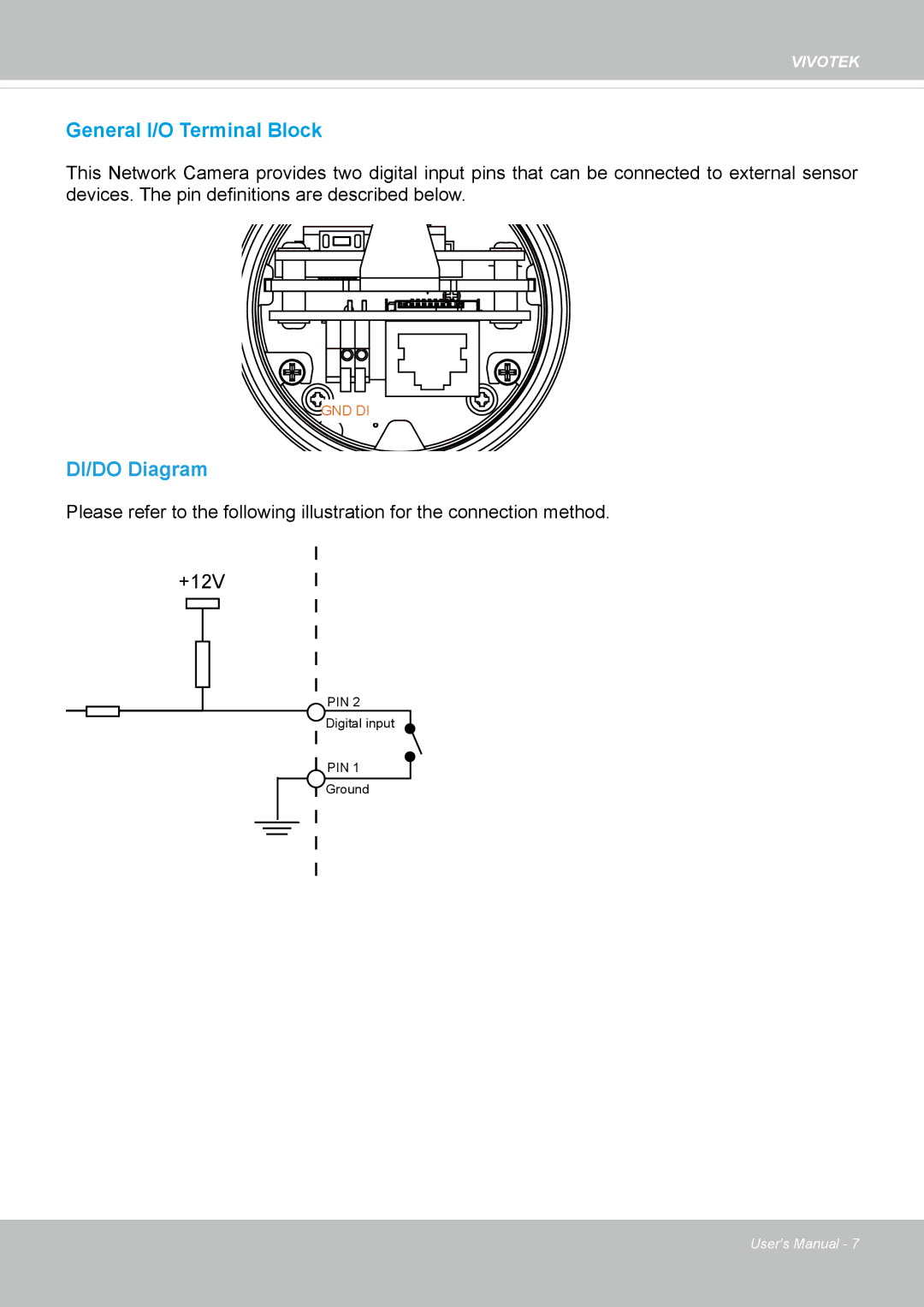
DI/DO Diagram
Please refer to the following illustration for the connection method.
+12V
PIN 2
Digital input
PIN 1
Ground
User's Manual - 7