VHX SERIES STEAMERS - REMOVAL AND REPLACEMENT OF PARTS
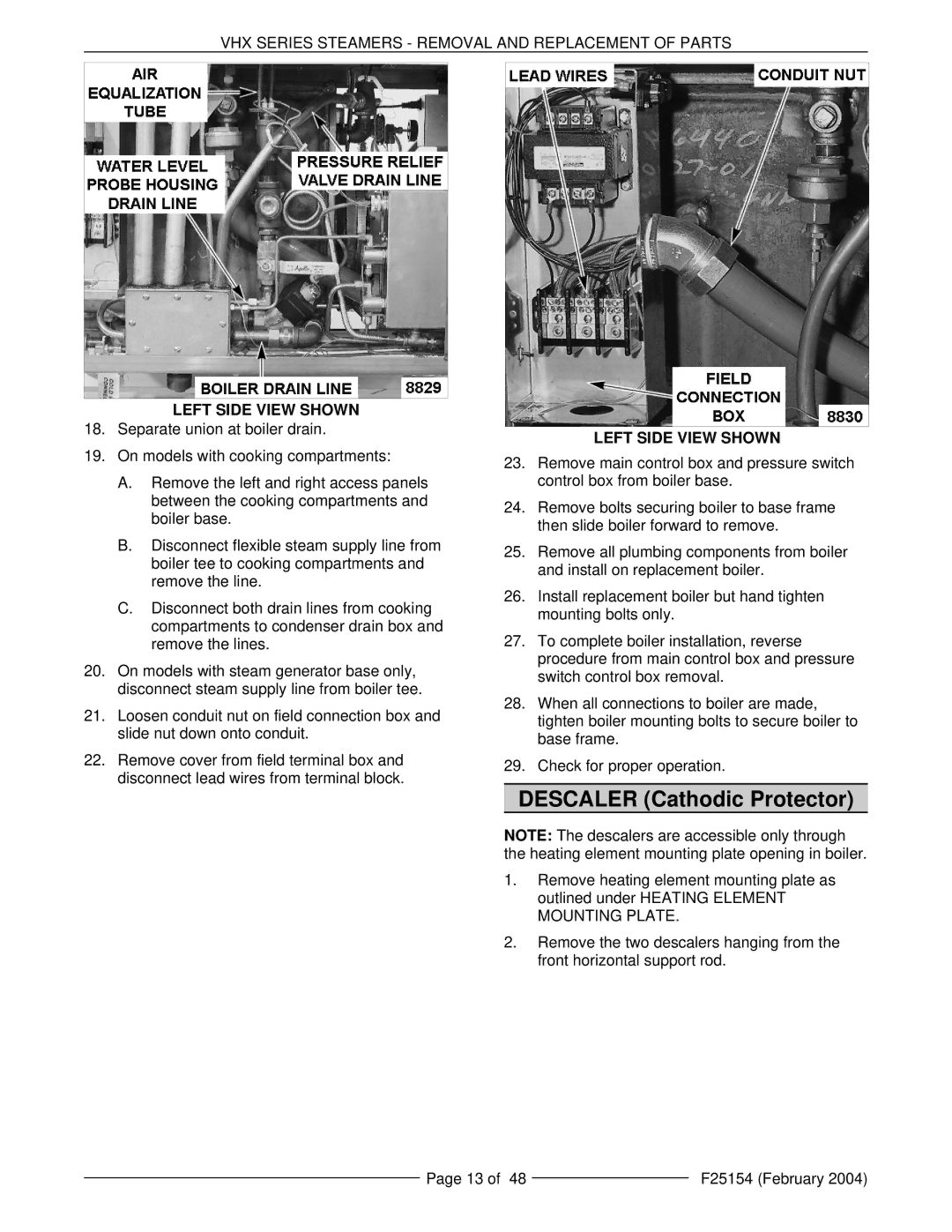
LEFT SIDE VIEW SHOWN
18.Separate union at boiler drain.
19.On models with cooking compartments:
A.Remove the left and right access panels between the cooking compartments and boiler base.
B.Disconnect flexible steam supply line from boiler tee to cooking compartments and remove the line.
C.Disconnect both drain lines from cooking compartments to condenser drain box and remove the lines.
20.On models with steam generator base only, disconnect steam supply line from boiler tee.
21.Loosen conduit nut on field connection box and slide nut down onto conduit.
22.Remove cover from field terminal box and disconnect lead wires from terminal block.
LEFT SIDE VIEW SHOWN
23.Remove main control box and pressure switch control box from boiler base.
24.Remove bolts securing boiler to base frame then slide boiler forward to remove.
25.Remove all plumbing components from boiler and install on replacement boiler.
26.Install replacement boiler but hand tighten mounting bolts only.
27.To complete boiler installation, reverse procedure from main control box and pressure switch control box removal.
28.When all connections to boiler are made, tighten boiler mounting bolts to secure boiler to base frame.
29.Check for proper operation.
DESCALER (Cathodic Protector)
NOTE: The descalers are accessible only through the heating element mounting plate opening in boiler.
1.Remove heating element mounting plate as outlined under HEATING ELEMENT MOUNTING PLATE.
2.Remove the two descalers hanging from the front horizontal support rod.
Page 13 of 48 |
| F25154 (February 2004) |
|