VHX SERIES STEAMER - SERVICE PROCEDURES AND ADJUSTMENTS
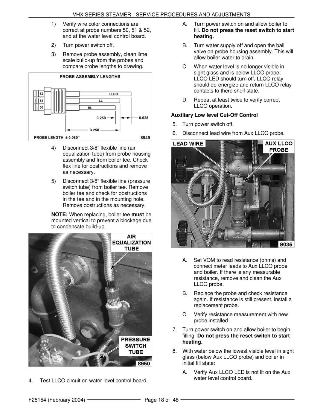
1)Verify wire color connections are correct at probe numbers 50, 51 & 52, and at the water level control board.
2)Turn power switch off.
3)Remove probe assembly, clean lime scale
4)Disconnect 3/8” flexible line (air equalization tube) from probe housing assembly and from boiler tee. Check flex line for obstructions and remove as necessary.
5)Disconnect 3/8” flexible line (pressure switch tube) from boiler tee. Remove boiler tee and check for obstructions in the tee and in the mounting hole. Remove obstructions as necessary.
NOTE: When replacing, boiler tee must be mounted vertical to prevent a blockage due to condensate
4.Test LLCO circuit on water level control board.
A.Turn power switch on and allow boiler to fill. Do not press the reset switch to start heating.
B.Turn water supply off and open the ball valve on probe housing assembly. This will allow boiler water to drain.
C.When water level is no longer visible in sight glass and is below LLCO probe; LLCO LED should turn off, LLCO relay should
D.Repeat at least twice to verify correct LLCO operation.
Auxiliary Low level Cut-Off Control
5.Turn power switch off.
6.Disconnect lead wire from Aux LLCO probe.
A.Set VOM to read resistance (ohms) and connect meter leads to Aux LLCO probe and boiler. If there is any measurable resistance, remove and clean the Aux LLCO probe.
B.Replace the probe and check resistance again. If resistance is still present, install a replacement probe.
C.Verify resistance measurement with new probe installed.
7.Turn power switch on and allow boiler to begin filling. Do not press the reset switch to start heating.
8.With water below the lowest visible level in sight glass (below Aux LLCO probe) and boiler in initial fill state:
A.Verify Aux LLCO LED is not lit on the Aux water level control board.
F25154 (February 2004) |
| Page 18 of 48 |
|
