www.vxitech.com

+5 V STANDBY USAGE

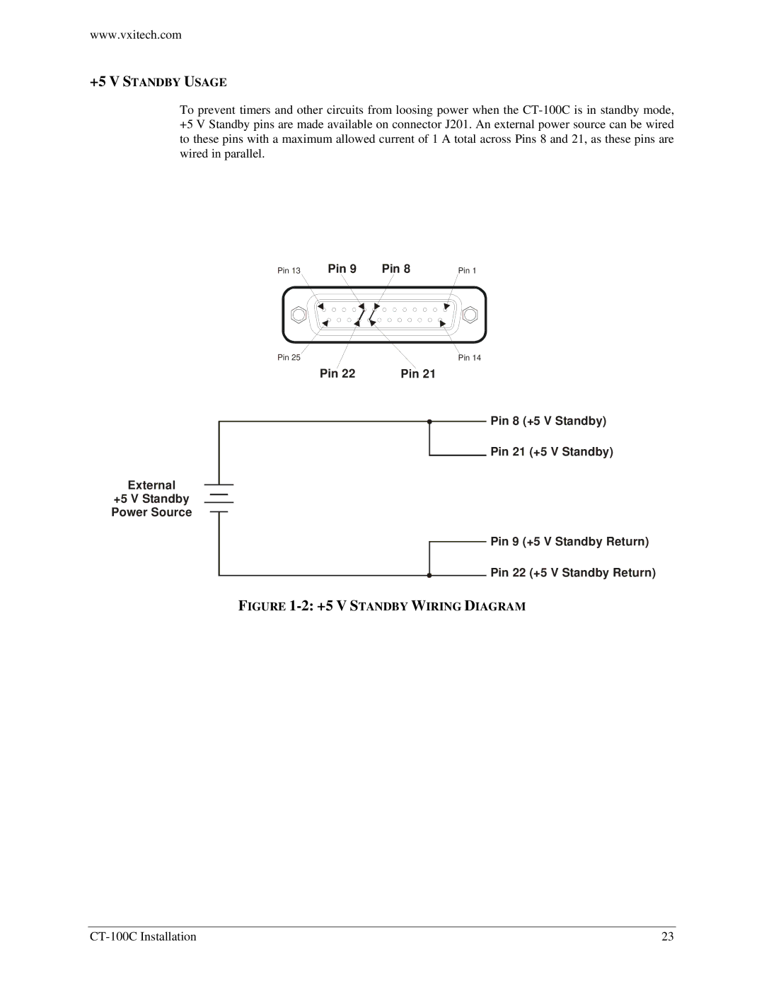
To prevent timers and other circuits from loosing power when the CT-100C is in standby mode, +5 V Standby pins are made available on connector J201. An external power source can be wired to these pins with a maximum allowed current of 1 A total across Pins 8 and 21, as these pins are wired in parallel.

Pin 13

Pin 9

Pin 8

Pin 1


Pin 25

Pin 14

Pin 22

Pin 21

Pin 8 (+5 V Standby)

Pin 21 (+5 V Standby)

External

+5 V Standby

Power Source

Pin 9 (+5 V Standby Return)

Pin 22 (+5 V Standby Return)

FIGURE 1-2: +5 V STANDBY WIRING DIAGRAM

CT-100C Installation

23

Page 23
Image 23
VXI CT-100C Series Six-Slot VXIBus Chassis, 82-0102-000 user manual +5 V Standby Usage, +5 V Standby Wiring Diagram