VXI Technology, Inc.
TABLE | |||
|
|
|
|
| Pin Number | Description |
|
| 1 | +5 V Monitor† |
|
| 2 |
| |
| 3 |
| |
| 4 |
| |
| 5 | Remote Power Switch |
|
| 6 | +5 V Output‡ |
|
| 7 | +12 V Output‡ |
|
| 8 | +5 V Standby Input |
|
| 9 | Ground |
|
| 10 | Backplane Reset I/O |
|
| 11 | N/C |
|
| 12 | N/C |
|
| 13 | Fan OK Output |
|
| 14 | +12 V Monitor† |
|
| 15 | +24 V Monitor† |
|
| 16 |
| |
| 17 | Ground |
|
| 18 | Remote Power Switch Return |
|
| 19 | Ground |
|
| 20 | Ground |
|
| 21 | +5 V Standby |
|
| 22 | Ground |
|
| 23 | AC Fail I/O |
|
| 24 | Ground |
|
| 25 | N/C |
|
NOTE | Monitor lines function as outputs only. |
| ‡ Pin 6 and Pin 7 (+5 V Output and +12 V Output, respectively) can provide 0.5 A from the |
| power supply. |
| Both jackscrews connect to ground. |
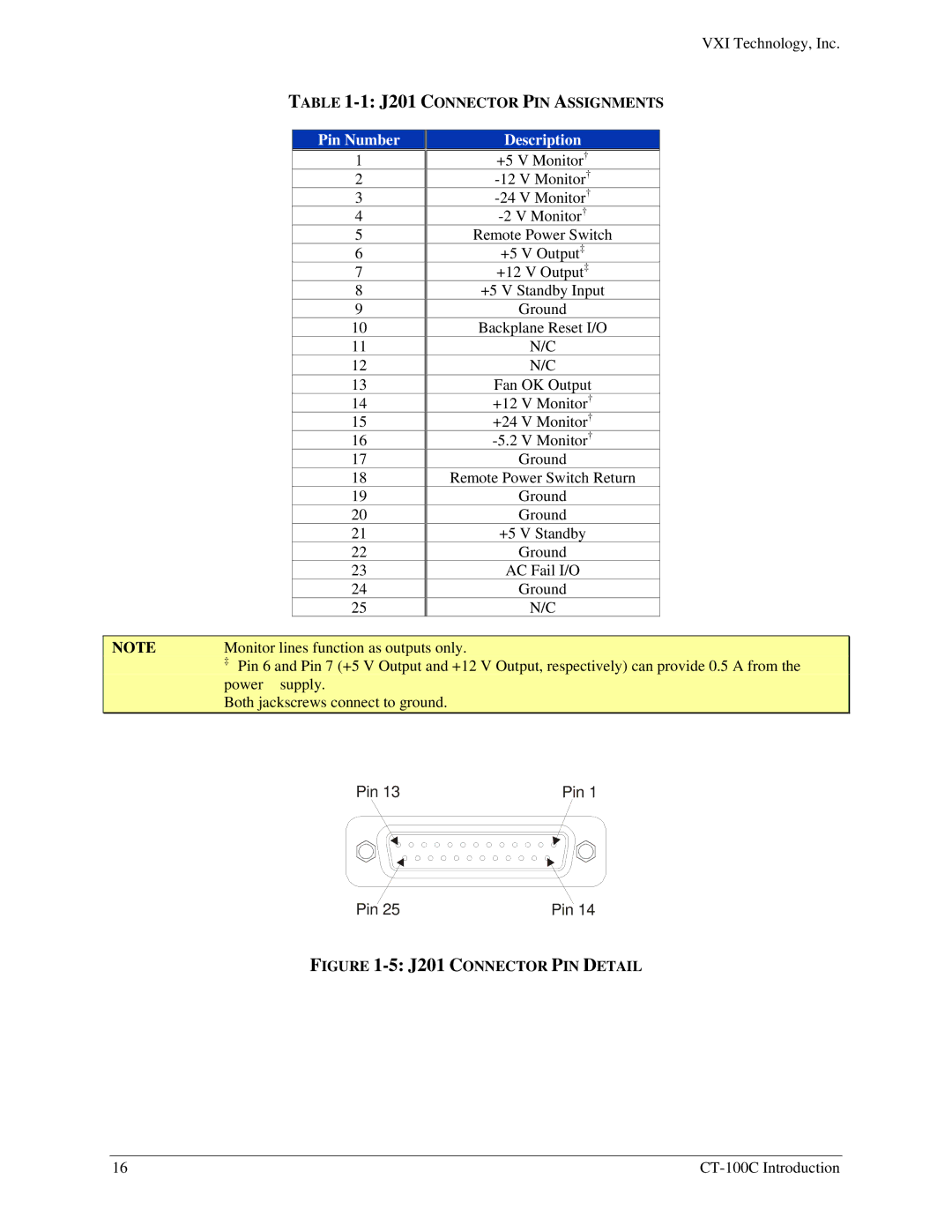
Pin 13 | Pin 1 |
Pin 25 | Pin 14 |
FIGURE 1-5: J201 CONNECTOR PIN DETAIL
16 |