VXI Technology, Inc.
POWER SPECIFICATIONS
USEABLE POWER
500 W to 50 °C, derated by 2.5%/ °C above 50 °C
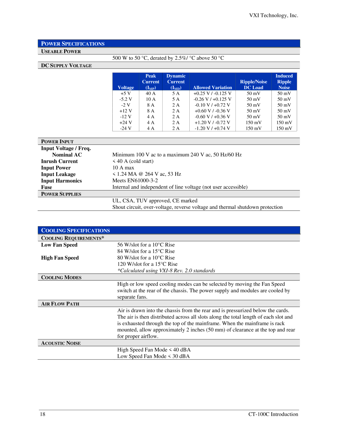
DC SUPPLY VOLTAGE
|
| Peak | Dynamic |
|
| Induced |
|
|
| Current | Current |
| Ripple/Noise | Ripple |
|
| Voltage | (IMP) | (IMD) | Allowed Variation | DC Load | Noise |
|
| +5 V | 40 A | 5 A | +0.25 V / | 50 mV | 50 mV |
|
| 10 A | 5 A | 50 mV | 50 mV |
| ||
| 8 A | 2 A | 50 mV | 50 mV |
| ||
| +12 V | 8 A | 2 A | +0.60 V / | 50 mV | 50 mV |
|
| 4 A | 2 A | 50 mV | 50 mV |
| ||
| +24 V | 4 A | 2 A | +1.20 V / | 150 mV | 150 mV |
|
| 4 A | 2 A | 150 mV | 150 mV |
| ||
|
|
|
|
|
|
|
|
POWER INPUT |
|
|
|
|
|
|
|
Input Voltage / Freq. | Minimum 100 V ac to a maximum 240 V ac, 50 Hz/60 Hz |
|
| ||||
Nominal AC |
|
| |||||
Inrush Current | < 40 A (cold start) |
|
|
|
|
| |
Input Power | 10 A max |
|
|
|
|
|
|
Input Leakage | < 1.24 MA @ 264 V ac, 53 Hz |
|
|
|
| ||
Input Harmonics | Meets |
|
|
|
|
| |
Fuse | Internal and independent of line voltage (not user accessible) |
|
| ||||
POWER SUPPLIES |
|
|
|
|
|
|
|
| UL, CSA, TUV approved, CE marked |
|
|
| |||
| Shout circuit, |
| |||||
|
|
|
|
|
|
|
|
COOLING SPECIFICATIONS |
|
|
|
|
|
|
|
COOLING REQUIREMENTS* |
|
|
|
|
|
|
|
Low Fan Speed | 56 W/slot for a 10°C Rise |
|
|
|
| ||
| 84 W/slot for a 15°C Rise |
|
|
|
| ||
High Fan Speed | 80 W/slot for a 10°C Rise |
|
|
|
| ||
120 W/slot for a 15°C Rise
*Calculated using VXI-8 Rev. 2.0 standards
COOLING MODES
High or low speed cooling modes can be selected by moving the Fan Speed switch at the rear of the chassis. The power supply and modules are cooled by separate fans.
AIR FLOW PATH
Air is drawn into the chassis from the rear and is pressurized below the cards. The air is then distributed across all slots along the total length of each slot and is exhausted through the top of the mainframe. When the mainframe is rack mounted, allow approximately 2 inches (50 mm) of clearance at the top and rear for proper airflow.
ACOUSTIC NOISE
High Speed Fan Mode < 40 dBA
Low Speed Fan Mode < 30 dBA
18 |