ADJUSTMENTS
CAUTION:Never ofiempt to
fhe lillerwhilethe engine is runningAlwoys. stop lhe engineond disconneclthe wirelromtn6 spoit plug before ottemplingto moke odjustments.
ROTATE
CLAMP CAP SCRE\
BELT ADJUSTMENTS
TINE DBIVE BELT
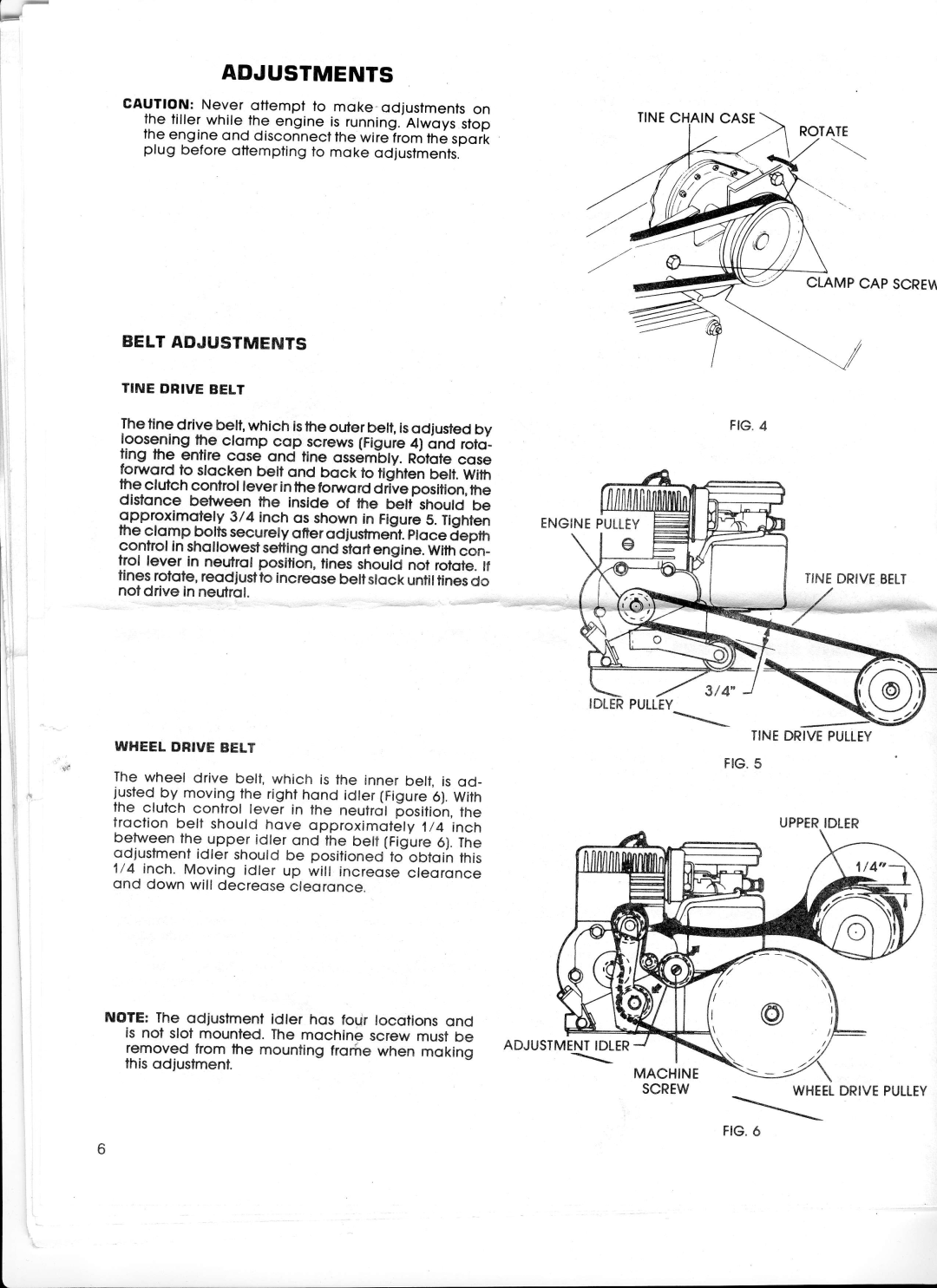
The tine drive belt, which isthe outer be[, isodjusted by the ctomp cop screws(Figuie4) onct roto_
l9_9s9ning
ang me enflre cose qnd tine ossembly.R6lotecose fonrord to stocken belt ond bock to fidnten belt,With the clutch control lever inthe forword drlve position,the disfonce between the inside of fhe betf shoutd be $Pproximotely 3/4 inch os shown in Figure5. Tighten the clo.mp bolts securety ofter od justmeit. etoce jepm control in shollowestsettingond itortensine. Withcbn_ trol lever in neutrol position,tinesshoult not rofote.lf flnesrotote,reodjusttoincreqsebellslock untiltinesdo notdrive in neutrol.
FIG.4
ENGINEPULLEY
c
TINEDRIVEBELT
3t4
WHEELDRIVEBELT
The wheel drive belt, which is the inner beli, is od_ justedby.movingthe righthond idter(Figure6).With the clutch confrol lever in the neutrcjl[ositioh, tfre troclion belt should hove opproximoiely1/4 inch betweenthe upper idler ond the belf (Figure6).The
qdiustment shouldbe
idleroOtqihthis 1/4 inch. Moving idler up will increosecteoronce ond down will decreosecleoronce.
NOTE:The odjustmentidler hos four locotionsond is nol sloi mounted.The mochine screw mustbe removed from the mounting frorire when moking this odjustmenl.
TINEDRIVEPULLEY
FIG5.
UPPERIDLER
ADJUSTMENTIDLER
\
MACHINE
SCREWWHEELDRIVE PULLEY
\