INSTALLATION
Valve Description
1) | Gas cock knob |
2) | Manual high/low adjustment |
3) | Pilot Adjustment |
4) | Thermocouple Connection |
5) | Main Operator |
6) | Outlet Pressure Tap (Manifold Pressure) |
7) | Inlet Pressure Tap (Supply Pressure) |
8) | Pilot Outlet |
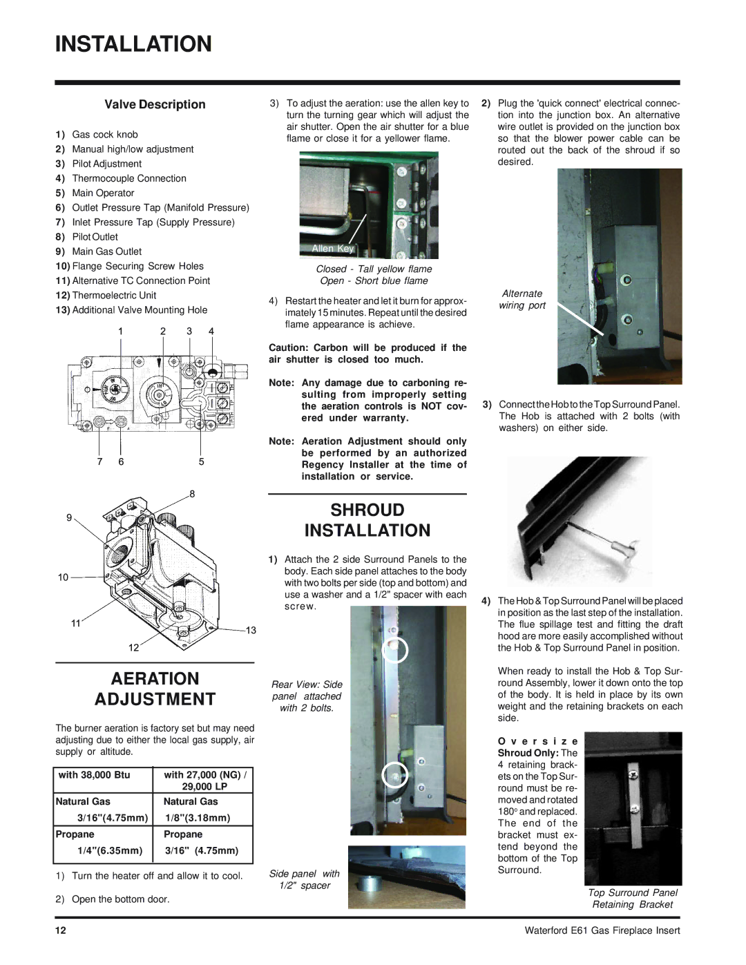
3) To adjust the aeration: use the allen key to | 2) Plug the 'quick connect' electrical connec- |
turn the turning gear which will adjust the | tion into the junction box. An alternative |
air shutter. Open the air shutter for a blue | wire outlet is provided on the junction box |
flame or close it for a yellower flame. | so that the blower power cable can be |
| routed out the back of the shroud if so |
| desired. |
9) Main Gas Outlet |
10) Flange Securing Screw Holes |
11) Alternative TC Connection Point |
12) Thermoelectric Unit |
13) Additional Valve Mounting Hole |
Allen Key
Closed - Tall yellow flame
Open - Short blue flame
4)Restart the heater and let it burn for approx- imately 15 minutes. Repeat until the desired flame appearance is achieve.
Caution: Carbon will be produced if the air shutter is closed too much.
Note: Any damage due to carboning re- sulting from improperly setting the aeration controls is NOT cov- ered under warranty.
Note: Aeration Adjustment should only be performed by an authorized Regency Installer at the time of installation or service.
Alternate
wiring port
3)Connect the Hob to the Top Surround Panel. The Hob is attached with 2 bolts (with washers) on either side.
AERATION
ADJUSTMENT
The burner aeration is factory set but may need adjusting due to either the local gas supply, air supply or altitude.
with 38,000 Btu | with 27,000 (NG) / |
| 29,000 LP |
Natural Gas | Natural Gas |
3/16"(4.75mm) | 1/8"(3.18mm) |
|
|
Propane | Propane |
1/4"(6.35mm) | 3/16" (4.75mm) |
|
|
1)Turn the heater off and allow it to cool.
2)Open the bottom door.
SHROUD
INSTALLATION
1)Attach the 2 side Surround Panels to the body. Each side panel attaches to the body with two bolts per side (top and bottom) and use a washer and a 1/2" spacer with each screw.
Rear View: Side panel attached with 2 bolts.
Side panel with
1/2" spacer
4)The Hob & Top Surround Panel will be placed in position as the last step of the installation. The flue spillage test and fitting the draft hood are more easily accomplished without the Hob & Top Surround Panel in position.
When ready to install the Hob & Top Sur- round Assembly, lower it down onto the top of the body. It is held in place by its own weight and the retaining brackets on each side.
O v e r s i z e Shroud Only: The 4 retaining brack- ets on the Top Sur- round must be re- moved and rotated 180o and replaced. The end of the bracket must ex- tend beyond the bottom of the Top Surround.
Top Surround Panel
Retaining Bracket
12 | Waterford E61 Gas Fireplace Insert |