INSTALLATION
OPTIONAL DOOR
GRILL
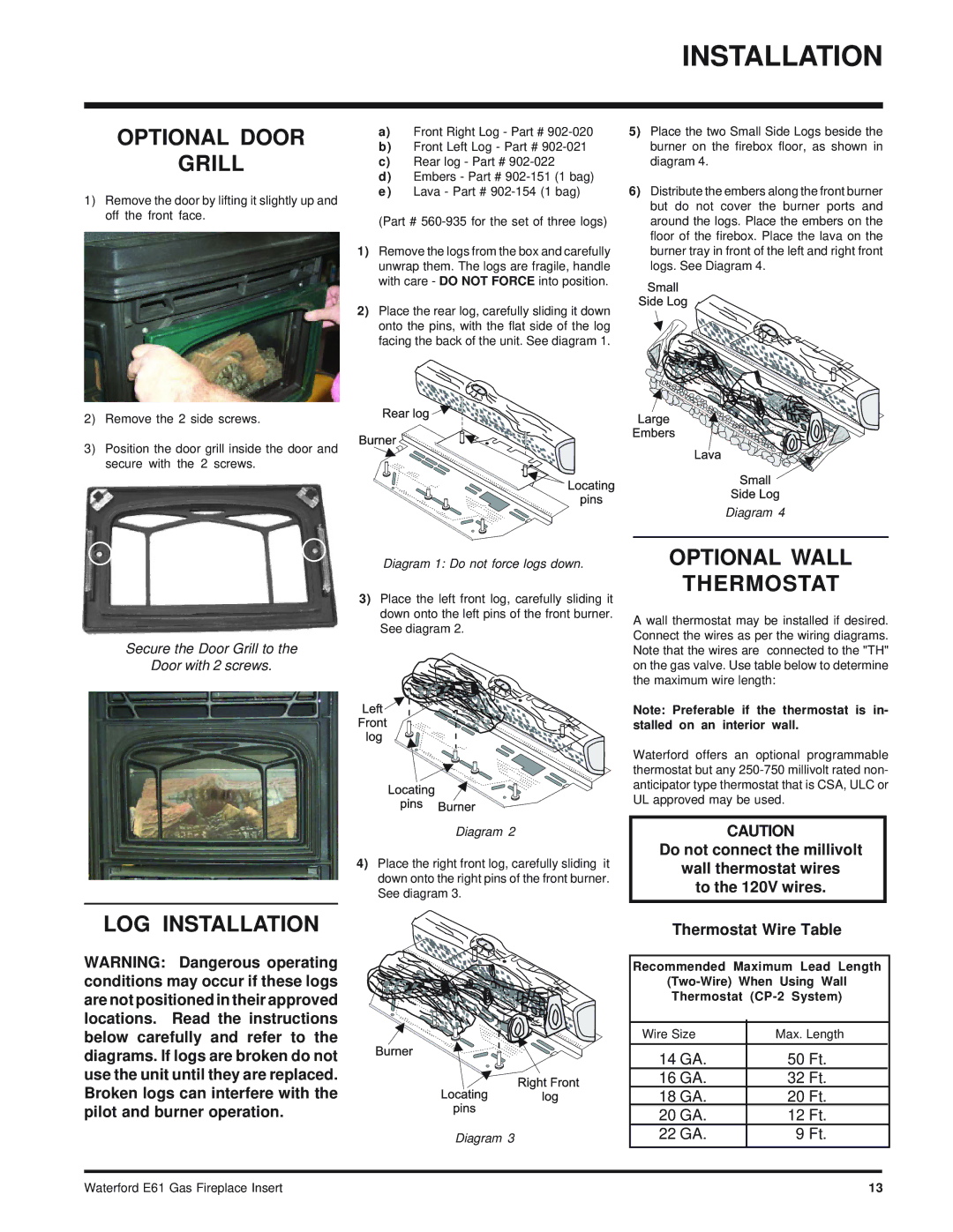
1)Remove the door by lifting it slightly up and off the front face.
2)Remove the 2 side screws.
3)Position the door grill inside the door and secure with the 2 screws.
a)Front Right Log - Part #
b)Front Left Log - Part #
c)Rear log - Part #
d)Embers - Part #
(Part #
1)Remove the logs from the box and carefully unwrap them. The logs are fragile, handle with care - DO NOT FORCE into position.
2)Place the rear log, carefully sliding it down onto the pins, with the flat side of the log facing the back of the unit. See diagram 1.
5)Place the two Small Side Logs beside the burner on the firebox floor, as shown in diagram 4.
6)Distribute the embers along the front burner but do not cover the burner ports and around the logs. Place the embers on the floor of the firebox. Place the lava on the burner tray in front of the left and right front logs. See Diagram 4.
Secure the Door Grill to the
Door with 2 screws.
LOG INSTALLATION
WARNING: Dangerous operating conditions may occur if these logs are not positioned in their approved locations. Read the instructions below carefully and refer to the diagrams. If logs are broken do not use the unit until they are replaced. Broken logs can interfere with the pilot and burner operation.
Diagram 1: Do not force logs down.
3)Place the left front log, carefully sliding it down onto the left pins of the front burner. See diagram 2.
Diagram 2
4)Place the right front log, carefully sliding it down onto the right pins of the front burner. See diagram 3.
Diagram 3
Diagram 4
OPTIONAL WALL
THERMOSTAT
A wall thermostat may be installed if desired. Connect the wires as per the wiring diagrams. Note that the wires are connected to the "TH" on the gas valve. Use table below to determine the maximum wire length:
Note: Preferable if the thermostat is in- stalled on an interior wall.
Waterford offers an optional programmable thermostat but any
CAUTION
Do not connect the millivolt
wall thermostat wires
to the 120V wires.
Thermostat Wire Table
Recommended Maximum Lead Length
Thermostat
Wire Size | Max. Length | |
|
|
|
14 GA. | 50 Ft. | |
16 GA. | 32 Ft. |
|
18 GA. | 20 Ft. | |
20 GA. | 12 Ft. | |
22 GA. | 9 Ft. | |
|
|
|
Waterford E61 Gas Fireplace Insert | 13 |