Installation
PACKAGE CONTENTS
The following items are supplied:
1FX82051 module
1Regulated switching power supply with four plug adapters (North American, Australian, U.K., and European configurations);
1Wall clip with two
1FX82051 Unmanaged Ethernet Switch Installation manual
SETTING
NOTE: As a matter of convenience, it is recommended that you verify the modes of operation for each
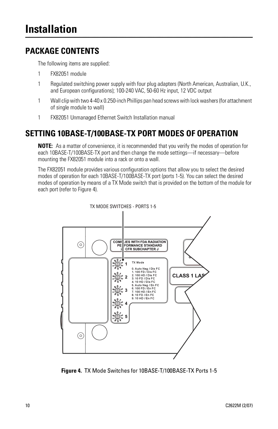
The FX82051 module provides various configuration options that allow you to select the desired modes of operation for each
TX MODE SWITCHES - PORTS
TX Mode
0. Auto Neg / Dis FC
1. 100 FD / Dis FC
2. 100 HD / Dis FC
3. 10 FD / Dis FC
4. 10 HD / Dis FC
5. Auto Neg / En FC
6. 100 FD / En FC
7. 100 HD / En FC
8. 10 FD / En FC
9. 10 HD / En FC
Figure 4. TX Mode Switches for 10BASE-T/100BASE-TX Ports 1-5
10 | C2622M (2/07) |
