REAR PANEL
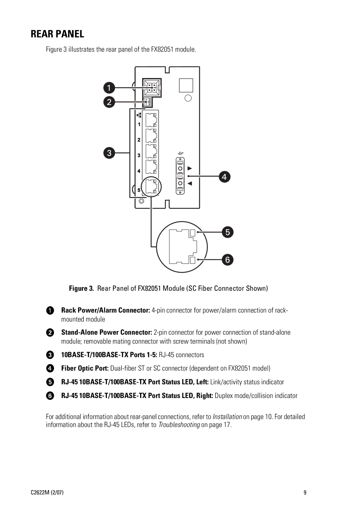
Figure 3 illustrates the rear panel of the FX82051 module.
Figure 3. Rear Panel of FX82051 Module (SC Fiber Connector Shown)
ìRack Power/Alarm Connector: 4-pin connector for power/alarm connection of rack- mounted module
îStand-Alone Power Connector: 2-pin connector for power connection of stand-alone module; removable mating connector with screw terminals (not shown)
ï10BASE-T/100BASE-TX Ports 1-5: RJ-45 connectors
ñFiber Optic Port: Dual-fiber ST or SC connector (dependent on FX82051 model)
óRJ-45 10BASE-T/100BASE-TX Port Status LED, Left: Link/activity status indicator
rRJ-45 10BASE-T/100BASE-TX Port Status LED, Right: Duplex mode/collision indicator
For additional information about rear-panel connections, refer to Installation on page 10. For detailed information about the RJ-45 LEDs, refer to Troubleshooting on page 17.