RUI/Gateway & DeviceNetTM
Configuration & Ladder Logic Example
Using an
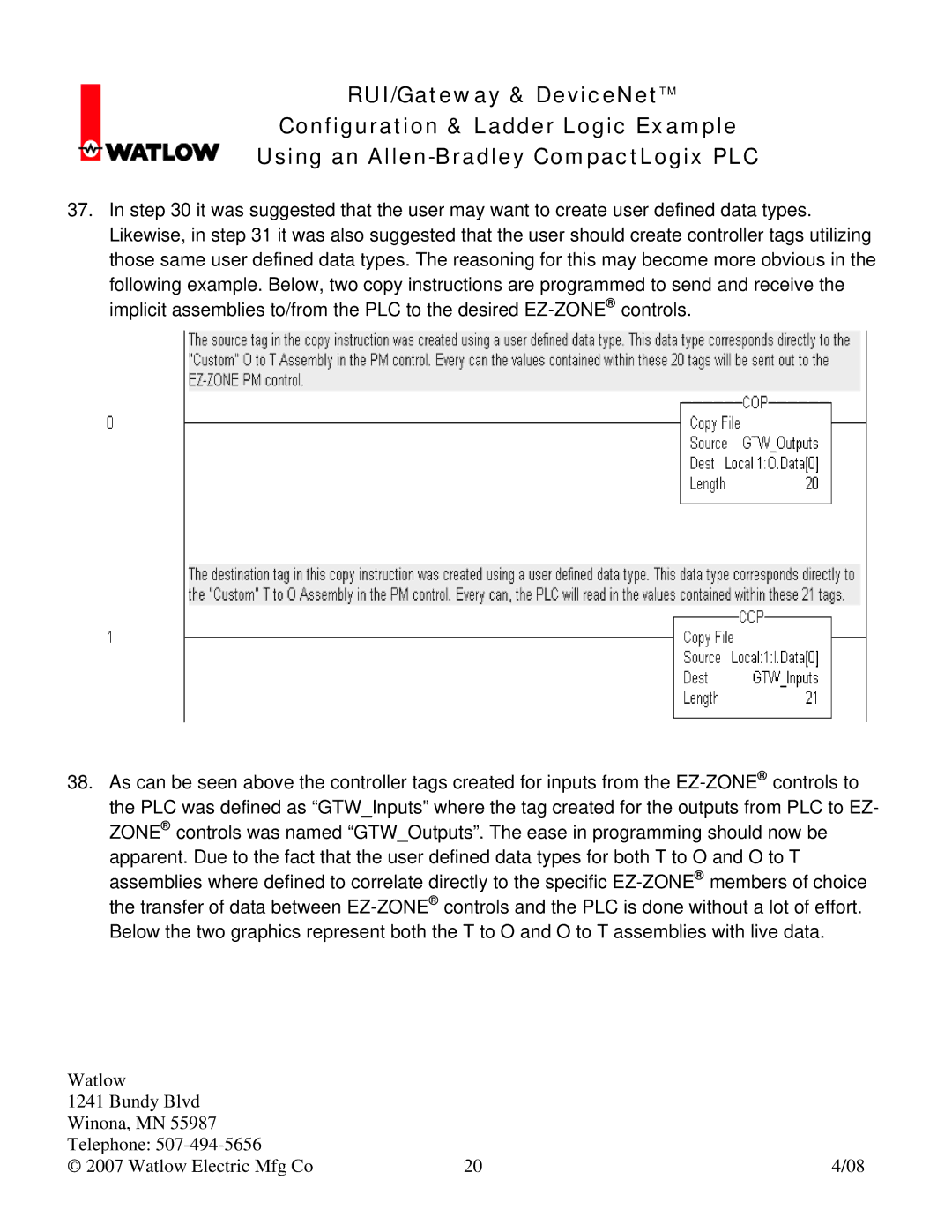
37.In step 30 it was suggested that the user may want to create user defined data types. Likewise, in step 31 it was also suggested that the user should create controller tags utilizing those same user defined data types. The reasoning for this may become more obvious in the
following example. Below, two copy instructions are programmed to send and receive the implicit assemblies to/from the PLC to the desired
38.As can be seen above the controller tags created for inputs from the
the PLC was defined as “GTW_Inputs” where the tag created for the outputs from PLC to EZ- ZONE® controls was named “GTW_Outputs”. The ease in programming should now be
apparent. Due to the fact that the user defined data types for both T to O and O to T assemblies where defined to correlate directly to the specific
Watlow |
|
|
1241 Bundy Blvd |
|
|
Winona, MN 55987 |
|
|
Telephone: |
|
|
© 2007 Watlow Electric Mfg Co | 20 | 4/08 |