Safety Guidelines
General Safety Information
GENERAL SAFETY
7.Personal Safety
General Safety Information Continued
Pre-Installation
PRESSURE SWITCH
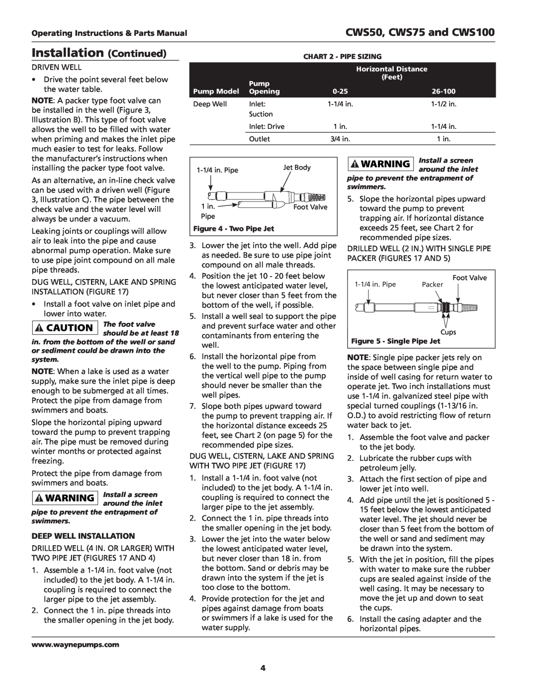
CWS50, CWS75 and CWS100
Installation
SHALLOW WELL INSTALLATION
Continued
PACKAGE SYSTEMS
Installation Continued
DEEP WELL INSTALLATION
CWS50, CWS75 and CWS100
Operating Instructions & Parts Manual
Electrical
Installation Continued
Maintenance
Electrical Continued
Operation
PRIMING THE SHALLOW WELL PUMP
Maintenance Continued
INSTALLING NEW SHAFT SEAL
PRE-CHARGEDTANK
LUBRICATION
ASPRING BLAKE STREAM, POND
C DUG WELL
E DRILLED WELL
D DRIVEN WELL
CWS50, CWS75 and CWS100
Troubleshooting Chart
Operating Instructions & Parts Manual
Replacement Parts List
Please provide following information
Address any correspondence to
Model number
Performance
Limited Warranty
ATTACH YOUR RECEIPT HERE
CWS50, CWS75 and CWS100
Operating Instructions & Parts Manual
Puit convertible Systèmes DEau De Pompe À Jet
Déballage
Directives de Sécurité
Généralités Sur La Sécurité
Pré-Installation
Généralités Sur La Sécurité Suite
CWS50, CWS75 et CWS100
Instructions D’utilisation et Manual de Pièces
Pré-Installation Suite
INSTALLATION DE PUITS DE SURFACE
SYSTÈMES EN PAQUETS
PUITS
Installation Suite
INSTALLATION POUR PUITS PROFOND
16-Fr
CWS50, CWS75 et CWS100
Électrique Suite
17-Fr
Installation Suite
CWS50, CWS75 et CWS100
Fonctionnement
Entretien
AMORÇAGE DE LA POMPE POUR PUITS DE SURFACE
AMORÇAGE DE LA POMPE POUR PUITS PROFOND
INSTALLATION D’UN NOUVEAU JOINT D’ARBRE
Entretien Suite
RÉSERVOIRS SATURÉS D’EAU CHARGÉS D’AVANCE
RÉSERVOIR CHARGÉ D’AVANCE
C PUITS CREUSÉ
E PUITS FORÉ
À EAU
D PUITS ENFONCÉ
Tableau de dépannage
21-Fr
CWS50, CWS75 et CWS100
Instructions D’utilisation et Manual de Pièces
Liste de pièces de rechange
S’il vous plaît fournir l’information suivante
Adresser toute correspondance à
22-Fr
23-Fr
Performance
Pression de Décharge kPa
12,2
Garantie Limitée
24-Fr
CWS50, CWS75 et CWS100
Instructions D’utilisation et Manual de Pièces
Pozo convertible Sistemas de Agua Con
Bomba de Chorro
Descripción
Para Desempacar
Pre-Instalación
CWS50, CWS75, y CWS100
Manual de instrucciones de operación y piezas
FUENTES DE SUMINISTRO DE AGUA
Pre-Instalación Continued
Instalación
PAQUETES DE SISTEMAS
POZOS
Instalación Continued
INSTALACIÓN EN UN PROFUNDO
28-Sp
CWS50, CWS75, y CWS100
Eléctricas
29-Sp
Instalación Continued
CWS50, CWS75, y CWS100
Funcionamiento
Mantenimiento
CEBADO DE LA BOMBA PARA POZOS POCO PROFUNDOS
CEBADO DE LA BOMBA PARA POZOS PROFUNDOS
Eléctricas Continued
DRENAJE DEL TONQUE
PRECARGADO
PARA VOLVER A HACER FUNCIONAR LA BOMBA
32-Sp
Mantenimiento
CWS50, CWS75, y CWS100
Continued
Tabla de Identificación de Problemas
33-Sp
CWS50, CWS75, y CWS100
Manual de instrucciones de operación y piezas
Lista de Partes de Reparación
Sirvase darnos la siguiente información
Dirija toda la correspondencia a
Número del modelo
Rendimiento
35-Sp
Presión de Descarga bar
1,38
Garantía Limitada
ANEXE SU RECIBO AQUI
36-Sp
CWS50, CWS75, y CWS100