Operating Instructions & Parts ManualCWS50, CWS75 and CWS100
Installation (Continued) |
|
|
|
|
|
|
|
|
|
|
|
| Prime |
|
| Electrical | |||||||||||||||||||||||
| Pressure |
| Outlet |
|
|
|
|
|
|
| |||||||||||||||||||||||||||||
|
|
|
|
|
|
|
|
|
|
|
|
|
|
|
|
|
|
|
|
|
|
|
|
|
| Plug | To |
|
|
|
| ||||||||
7. Slope both pipes upward toward |
|
|
|
| Risk of electrical | ||||||||||||||||||||||||||||||||||
|
|
|
|
|
|
|
|
|
|
|
|
| |||||||||||||||||||||||||||
|
|
|
|
|
|
|
|
|
|
|
|
| |||||||||||||||||||||||||||
| Switch |
|
|
|
|
|
|
|
|
|
|
|
|
|
| ||||||||||||||||||||||||
|
|
|
|
|
|
|
|
|
|
| Suction |
|
|
| |||||||||||||||||||||||||
| the pump to eliminate trapping |
|
|
|
|
|
|
|
|
|
|
|
|
|
|
|
| shock. This pump is | |||||||||||||||||||||
|
|
|
|
|
|
|
|
|
|
|
|
|
|
|
|
|
|
| |||||||||||||||||||||
|
|
|
|
|
|
|
|
|
|
|
|
|
|
|
|
|
| ||||||||||||||||||||||
| air. If the horizontal distance |
|
|
|
|
|
|
|
|
|
|
|
|
|
|
| To Jet |
| designed for indoor installation only. | ||||||||||||||||||||
|
|
|
|
|
|
|
|
|
|
|
|
|
|
|
|
| |||||||||||||||||||||||
| exceeds 25 feet, see Chart 2 for the |
|
|
|
|
|
|
|
|
|
|
|
|
|
| Select the proper size wire and | |||||||||||||||||||||||
|
|
|
|
|
|
|
|
|
|
|
|
| |||||||||||||||||||||||||||
| recommended pipe sizes. |
|
|
|
|
|
|
|
|
|
|
|
|
|
|
| To Drive |
| fuse (Chart 3). Time delay fuses are | ||||||||||||||||||||
|
|
|
|
|
|
|
|
|
|
|
|
|
|
|
|
| |||||||||||||||||||||||
DEEP WELL PUMP WITH HORIZONTAL |
|
|
|
|
|
|
|
|
|
|
|
|
|
| recommended over standard fuses | ||||||||||||||||||||||||
AND VERTICAL STORAGE TANK |
|
|
|
|
|
|
|
|
|
| for motor circuit protection. All pump | ||||||||||||||||||||||||||||
(FIGURES 6 AND 7) |
|
|
|
|
|
|
|
|
|
|
|
|
|
|
|
|
|
|
| motors have | |||||||||||||||||||
|
|
|
|
|
|
|
|
|
|
|
|
|
|
| 3/4 HP an 1 HP |
|
| ||||||||||||||||||||||
|
|
|
|
|
|
|
|
|
|
|
|
|
|
|
|
|
|
|
|
|
|
|
|
|
|
| protection that will prevent damage to | ||||||||||||
| Prime |
|
|
| To Suction |
|
|
|
|
|
|
|
|
|
|
|
|
|
|
|
|
|
| ||||||||||||||||
|
|
|
| To Jet |
|
|
|
|
|
|
|
|
|
|
|
|
|
|
|
| the motor due to overheating. | ||||||||||||||||||
| Plug |
|
|
|
|
|
|
|
|
|
|
|
|
|
|
|
|
|
|
|
|
|
|
|
|
|
|
|
| ||||||||||
|
|
|
|
|
|
|
|
|
|
|
|
|
|
|
|
|
|
|
|
|
|
|
|
|
|
|
| ||||||||||||
| Pressure |
|
|
|
|
|
|
|
|
|
|
|
|
|
|
|
|
|
|
| Figure 8 - |
|
|
|
| Do not connect to | |||||||||||||
|
|
|
|
|
|
|
|
|
|
|
|
|
|
|
|
|
|
|
|
|
|
|
| ||||||||||||||||
|
|
|
|
|
|
|
|
|
|
|
|
|
|
|
|
|
|
|
| Air |
|
|
|
|
|
|
|
|
|
|
|
|
|
|
|
|
|
| electric power supply |
| Switch |
|
|
|
|
|
|
|
|
|
|
|
| Volume |
| 2. Check the pressure with the power | until unit is permanently grounded. | ||||||||||||||||||||||
|
|
|
|
|
|
|
|
|
|
|
|
|
|
|
|
|
|
| |||||||||||||||||||||
|
|
|
|
|
|
|
|
|
|
|
|
|
|
|
|
|
|
|
| off, faucets open and no water |
|
| |||||||||||||||||
|
|
|
|
|
|
|
|
|
|
|
|
|
|
|
|
|
|
| Control |
|
|
| Connect ground wire to approved ground | ||||||||||||||||
|
|
|
|
|
|
|
|
|
|
|
|
|
|
|
|
|
|
| Tubing |
| flowing (zero water pressure). |
|
| then connect terminal provided. | |||||||||||||||
|
|
|
|
|
|
|
|
|
|
|
|
|
|
|
|
|
|
|
|
|
| 3. Install a valve and isolator hose between | A metal underground water pipe or | ||||||||||||||||
|
|
|
|
|
|
|
|
|
|
|
|
|
|
|
|
|
|
| Air |
| the system and the house plumbing to | well casing at least 10 feet long makes | |||||||||||||||||
|
|
|
|
|
|
|
|
|
|
|
|
|
|
|
|
|
|
|
| aid in pump removal for servicing and | the best ground electrode. If plastic | ||||||||||||||||||
|
|
|
|
|
|
|
|
|
|
|
|
|
|
|
|
|
|
| |||||||||||||||||||||
|
| To Drive |
|
|
|
|
|
|
|
|
|
|
| Volume |
| for reducing noise transmitted to the | pipe or insulated fittings are used, run | ||||||||||||||||||||||
|
|
|
|
|
| Outlet Control |
| ||||||||||||||||||||||||||||||||
|
|
|
|
|
|
| house through the piping. |
|
| a wire directly to the metal well casing | |||||||||||||||||||||||||||||
| Figure 6 - Horizontal Tank |
|
|
|
|
| |||||||||||||||||||||||||||||||||
|
|
|
| 4. Provide a hose bib (faucet) at the |
|
| or use a ground electrode furnished by | ||||||||||||||||||||||||||||||||
|
|
|
|
|
|
|
|
|
|
|
|
|
|
|
|
|
|
|
|
|
|
|
| ||||||||||||||||
|
|
|
|
|
|
|
|
|
|
|
|
|
|
|
|
|
|
|
|
|
|
| |||||||||||||||||
|
|
|
|
|
|
|
|
|
|
|
|
|
|
|
|
|
|
|
|
|
| lowest point in the system to drain | the power company. | ||||||||||||||||
|
|
|
|
|
|
|
|
|
|
|
|
|
|
|
|
| Air Volume | ||||||||||||||||||||||
| Air Volume Control |
|
|
|
|
|
|
|
| for service or storage. |
|
|
|
|
|
|
| ||||||||||||||||||||||
|
|
|
|
|
|
| Control Tubing |
|
|
|
|
| There is only one proper ground | ||||||||||||||||||||||||||
|
|
|
|
|
|
| Hose |
|
|
| CONVERTING THE DEEP WELL PUMP TO | terminal on the unit. The terminal(s) is | |||||||||||||||||||||||||||
|
|
|
|
|
|
| To |
| SHALLOW WELL OPERATION (FIGURE 9) |
| located under the pressure switch cover, | ||||||||||||||||||||||||||||
| Outlet |
|
|
|
|
| Coupling |
| |||||||||||||||||||||||||||||||
|
| Suction |
|
|
|
|
|
|
|
|
|
|
|
| To Air Volume | is painted green and is identified as | |||||||||||||||||||||||
|
|
|
|
|
|
|
|
|
|
|
|
|
| ||||||||||||||||||||||||||
|
|
|
|
|
|
|
|
|
|
|
|
|
|
|
|
|
|
|
|
|
|
|
|
|
|
|
|
|
|
| |||||||||
|
|
|
|
|
|
|
|
|
|
|
|
|
|
|
|
|
|
|
|
|
|
|
|
|
|
|
|
|
|
| |||||||||
|
|
|
|
|
|
|
|
|
|
|
|
|
|
|
|
|
|
|
|
|
|
|
|
|
|
|
|
|
|
|
|
| Control |
|
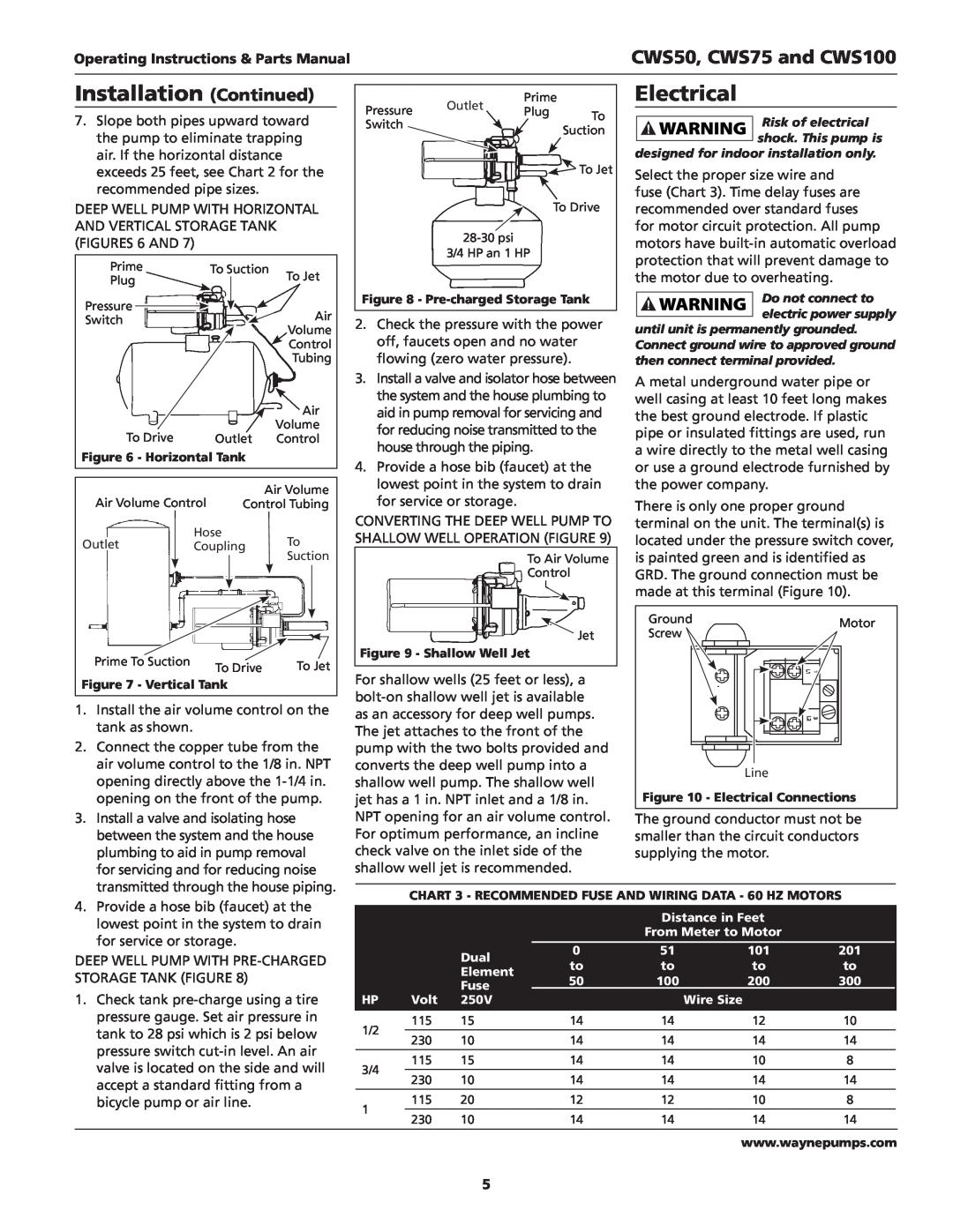
| GRD. The ground connection must be | |||
|
|
|
|
|
|
|
|
|
|
|
|
|
|
|
|
|
|
|
|
|
|
|
|
|
|
|
|
|
|
|
|
|
|
| |||||
|
|
|
|
|
|
|
|
|
|
|
|
|
|
|
|
|
|
|
|
|
|
|
|
|
|
|
|
|
|
|
|
|
|
|
|
| made at this terminal (Figure 10). | ||
|
|
|
|
|
|
|
|
|
|
|
|
|
|
|
|
|
|
|
|
|
|
|
|
|
|
|
|
|
|
|
|
|
|
|
|
| |||
|
|
|
|
|
|
|
|
|
|
|
|
|
|
|
|
|
|
|
|
|
|
|
|
|
|
|
|
|
|
|
|
|
|
|
|
| |||
|
|
|
|
|
|
|
|
|
|
|
|
|
|
|
|
|
|
|
|
|
|
|
|
|
|
|
|
|
|
|
|
|
|
|
|
|
|
|
|
|
|
|
|
|
|
|
|
|
|
|
|
|
|
|
|
|
|
|
|
|
|
|
|
|
|
|
|
|
|
|
|
|
|
|
|
|
|
|
|
|
|
|
|
|
|
|
|
|
|
|
|
|
|
|
|
|
|
|
|
|
|
|
|
|
|
|
|
|
|
|
|
|
|
|
|
|
|
|
|
|
|
|
| Ground | Motor | |
|
|
| Jet | Screw | ||
|
|
|
| |||
Prime To Suction | To Drive | To Jet | Figure 9 - Shallow Well Jet |
|
| |
| L1 |
| ||||
| For shallow wells (25 feet or less), a | 1 | ||||
Figure 7 - Vertical Tank |
|
|
| |||
|
|
| ||||
1. Install the air volume control on the |
|
| ||||
as an accessory for deep well pumps. | L2 | 3 | ||||
tank as shown. |
|
| The jet attaches to the front of the |
|
| |
2. Connect the copper tube from the | pump with the two bolts provided and |
|
| |||
air volume control to the 1/8 in. NPT | converts the deep well pump into a | Line |
| |||
opening directly above the | shallow well pump. The shallow well |
| ||||
Figure 10 - Electrical Connections | ||||||
opening on the front of the pump. | jet has a 1 in. NPT inlet and a 1/8 in. | |||||
3. Install a valve and isolating hose |
| NPT opening for an air volume control. | The ground conductor must not be | |||
between the system and the house | For optimum performance, an incline | smaller than the circuit conductors | ||||
plumbing to aid in pump removal | check valve on the inlet side of the | supplying the motor. |
| |||
for servicing and for reducing noise | shallow well jet is recommended. |
|
| |||
transmitted through the house piping. | CHART 3 - RECOMMENDED FUSE AND WIRING DATA - 60 HZ MOTORS | |||||
|
|
| ||||
4. Provide a hose bib (faucet) at the |
|
|
|
|
|
|
|
|
|
| |
|
|
|
|
| Distance in Feet |
|
| ||||
lowest point in the system to drain |
|
|
|
|
|
|
| ||||
|
|
|
|
| From Meter to Motor |
|
| ||||
for service or storage. |
|
|
|
|
|
|
| ||||
|
| Dual | 0 |
| 51 |
| 101 |
| 201 | ||
|
|
|
|
| |||||||
DEEP WELL PUMP WITH |
|
|
|
|
| ||||||
|
| to |
| to |
| to |
| to | |||
STORAGE TANK (FIGURE 8) |
|
| Element |
|
|
| |||||
|
| 50 |
| 100 |
| 200 |
| 300 | |||
|
| Fuse |
|
|
| ||||||
1. Check tank |
|
|
|
|
|
|
|
|
| ||
HP | Volt | 250V |
|
|
| Wire Size |
|
| |||
pressure gauge. Set air pressure in | 1/2 | 115 | 15 | 14 | 14 | 12 | 10 | ||||
tank to 28 psi which is 2 psi below |
|
|
|
|
|
|
|
|
| ||
230 | 10 | 14 | 14 | 14 | 14 | ||||||
pressure switch |
| ||||||||||
| 115 | 15 | 14 | 14 | 10 | 8 | |||||
valve is located on the side and will | 3/4 | ||||||||||
230 | 10 | 14 | 14 | 14 | 14 | ||||||
accept a standard fitting from a |
| ||||||||||
| 115 | 20 | 12 | 12 | 10 | 8 | |||||
bicycle pump or air line. | 1 | ||||||||||
| 230 | 10 | 14 | 14 | 14 | 14 | |||||
|
| ||||||||||
|
|
|
|
|
|
|
|
|
|
| |
www.waynepumps.com
5