FRAME ASSEMBLY
ARM ASSEMBLY
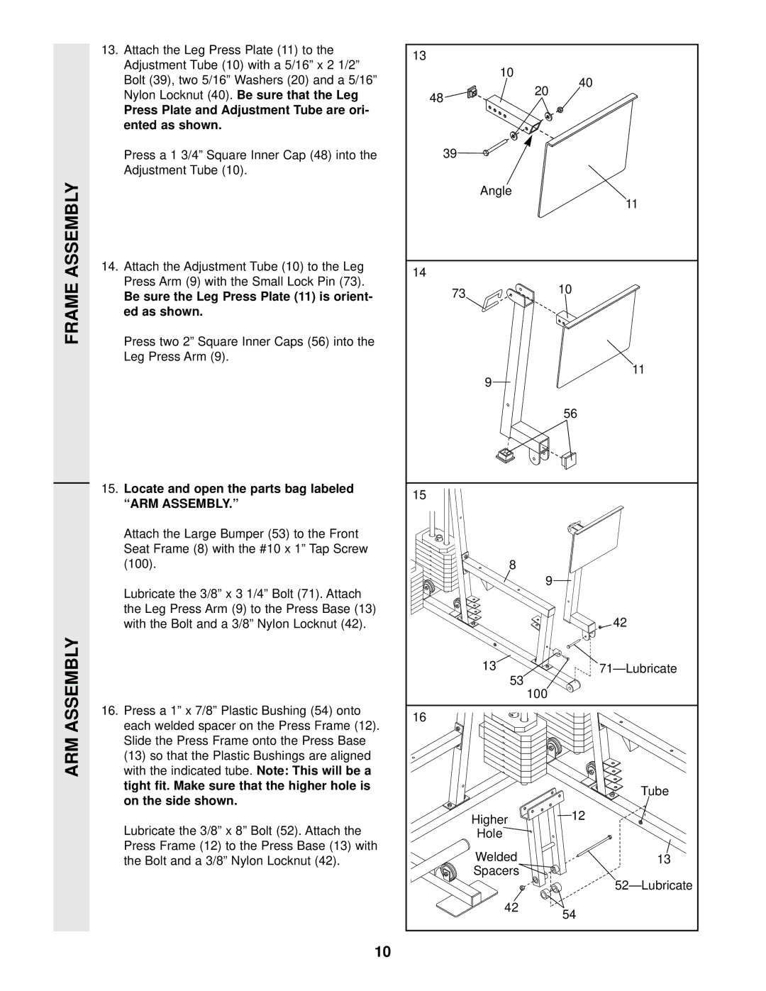
13. Attach the Leg Press Plate (11) to the | 13 |
|
|
Adjustment Tube (10) with a 5/16” x 2 1/2” |
|
| |
10 |
|
| |
Bolt (39), two 5/16” Washers (20) and a 5/16” |
| 40 | |
| 20 | ||
Nylon Locknut (40). Be sure that the Leg | 48 |
| |
|
| ||
Press Plate and Adjustment Tube are ori- |
|
|
|
ented as shown. |
|
|
|
Press a 1 3/4” Square Inner Cap (48) into the | 39 |
|
|
Adjustment Tube (10). |
|
|
|
| Angle |
| 11 |
|
|
| |
14. Attach the Adjustment Tube (10) to the Leg | 14 |
|
|
Press Arm (9) with the Small Lock Pin (73). |
|
| |
73 |
| 10 | |
Be sure the Leg Press Plate (11) is orient- |
| ||
|
| ||
ed as shown. |
|
|
|
Press two 2” Square Inner Caps (56) into the |
|
|
|
Leg Press Arm (9). |
|
| 11 |
| 9 |
| |
|
|
| |
|
|
| 56 |
15. Locate and open the parts bag labeled | 15 |
|
|
“ARM ASSEMBLY.” |
|
| |
|
|
| |
Attach the Large Bumper (53) to the Front |
|
|
|
Seat Frame (8) with the #10 x 1” Tap Screw |
|
|
|
(100). | 8 |
|
|
Lubricate the 3/8” x 3 1/4” Bolt (71). Attach |
| 9 |
|
|
|
| |
the Leg Press Arm (9) to the Press Base (13) |
|
| 42 |
with the Bolt and a 3/8” Nylon Locknut (42). |
|
| |
| 13 |
| |
| 53 | 100 |
|
|
|
| |
16. Press a 1” x 7/8” Plastic Bushing (54) onto | 16 |
|
|
each welded spacer on the Press Frame (12). |
|
| |
|
|
| |
Slide the Press Frame onto the Press Base |
|
|
|
(13) so that the Plastic Bushings are aligned |
|
|
|
with the indicated tube. Note: This will be a |
|
|
|
tight fit. Make sure that the higher hole is |
|
| Tube |
on the side shown. |
|
| |
|
|
| |
| Higher |
| 12 |
Lubricate the 3/8” x 8” Bolt (52). Attach the |
|
| |
Hole |
|
| |
Press Frame (12) to the Press Base (13) with | Welded |
| 13 |
the Bolt and a 3/8” Nylon Locknut (42). |
| ||
| Spacers |
|
|
|
|
| |
| 42 |
| 54 |
|
|
|
10