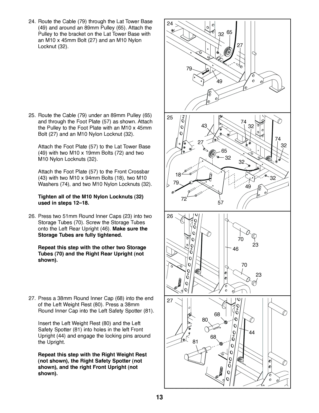
24. Route the Cable (79) through the Lat Tower Base | 24 |
| |
(49) and around an 89mm Pulley (65). Attach the |
| ||
| 32 65 | ||
Pulley to the bracket on the Lat Tower Base with |
| ||
an M10 x 45mm Bolt (27) and an M10 Nylon |
| 27 | |
Locknut (32). |
| ||
| 79 |
| |
|
| 49 | |
25. Route the Cable (79) under an 89mm Pulley (65) | 25 |
| |
and through the Foot Plate (57) as shown. Attach | 74 | ||
43 | |||
the Pulley to the Foot Plate with an M10 x 45mm | 32 | ||
Bolt (27) and an M10 Nylon Locknut (32). |
| 74 | |
| 27 | ||
Attach the Foot Plate (57) to the Lat Tower Base | 32 | ||
| |||
(49) with two M10 x 19mm Bolts (72) and two |
| 65 | |
| 32 | ||
M10 Nylon Locknuts (32). |
| ||
|
| 32 | |
Attach the Foot Plate (57) to the Front Crossbar | 18 |
| |
(43) with two M10 x 94mm Bolts (18), two M10 | 32 | ||
79 | |||
Washers (74), and two M10 Nylon Locknuts (32). | 49 | ||
|
| ||
Tighten all of the M10 Nylon Locknuts (32) | 72 |
| |
used in steps | 57 | ||
| |||
26. Press two 51mm Round Inner Caps (23) into two | 26 |
| |
Storage Tubes (70). Screw the Storage Tubes |
|
| |
onto the Left Rear Upright (46). Make sure the |
|
| |
Storage Tubes are fully tightened. |
| 70 | |
|
| ||
Repeat this step with the other two Storage |
| 23 | |
| 46 | ||
Tubes (70) and the Right Rear Upright (not |
| ||
|
| ||
shown). |
| 70 | |
|
| ||
|
| 23 | |
27. Press a 38mm Round Inner Cap (68) into the end | 27 |
| |
of the Left Weight Rest (80). Press a 38mm |
| ||
|
| ||
Round Inner Cap into the Left Safety Spotter (81). |
| 68 | |
| 80 | ||
Insert the Left Weight Rest (80) and the Left |
| ||
|
| ||
Safety Spotter (81) into holes in the left Front |
| 44 | |
Upright (44) and engage the locking pins around |
| ||
81 | 68 | ||
the Upright. |
| ||
Repeat this step with the Right Weight Rest |
|
| |
(not shown), the Right Safety Spotter (not |
|
| |
shown), and the right Front Upright (not |
|
| |
shown). |
|
| |
| 13 |
|
