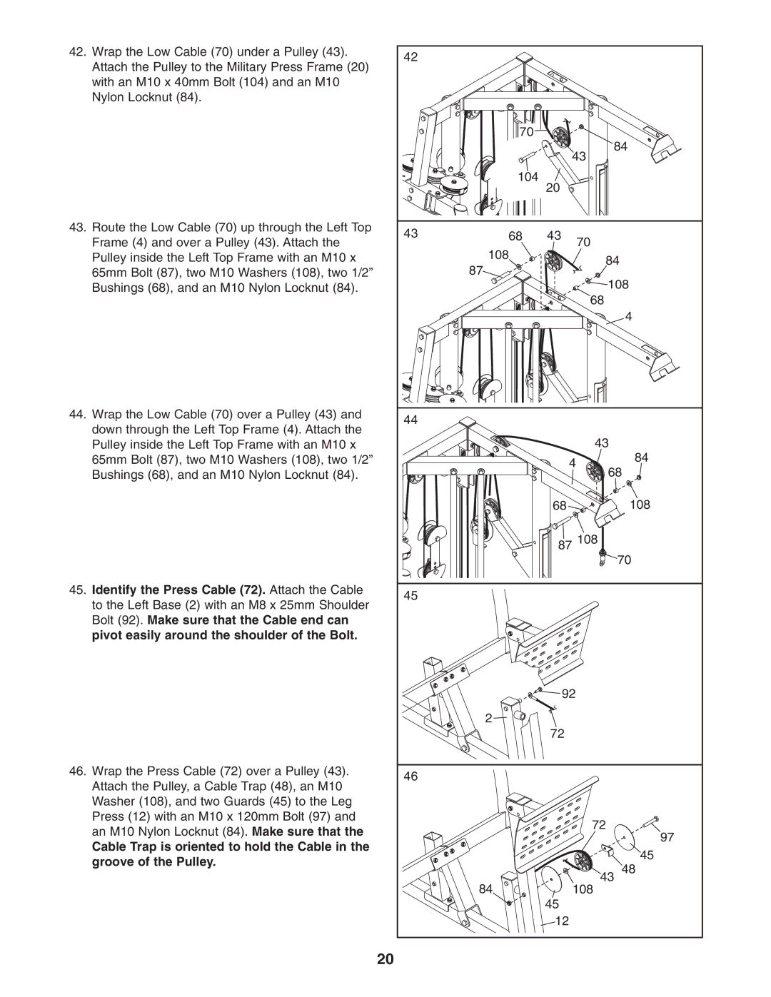
42.Wrap the Low Cable (70) under a Pulley (43). Attach the Pulley to the Military Press Frame (20) with an M10 x 40mm Bolt (104) and an M10 Nylon Locknut (84).
43.Route the Low Cable (70) up through the Left Top Frame (4) and over a Pulley (43). Attach the Pulley inside the Left Top Frame with an M10 x 65mm Bolt (87), two M10 Washers (108), two 1/2” Bushings (68), and an M10 Nylon Locknut (84).
44.Wrap the Low Cable (70) over a Pulley (43) and down through the Left Top Frame (4). Attach the Pulley inside the Left Top Frame with an M10 x 65mm Bolt (87), two M10 Washers (108), two 1/2” Bushings (68), and an M10 Nylon Locknut (84).
45.Identify the Press Cable (72). Attach the Cable to the Left Base (2) with an M8 x 25mm Shoulder Bolt (92). Make sure that the Cable end can pivot easily around the shoulder of the Bolt.
46.Wrap the Press Cable (72) over a Pulley (43). Attach the Pulley, a Cable Trap (48), an M10 Washer (108), and two Guards (45) to the Leg Press (12) with an M10 x 120mm Bolt (97) and an M10 Nylon Locknut (84). Make sure that the
Cable Trap is oriented to hold the Cable in the groove of the Pulley.
42 |
|
|
|
|
| 70 |
|
|
|
|
|
| 84 | |
|
|
| 43 |
|
| 104 | 20 |
|
|
|
|
|
| |
43 | 68 | 43 | 70 |
|
| 108 |
|
| |
|
| 84 | ||
| 87 |
| ||
|
| 108 | ||
|
|
| ||
|
|
| 68 |
|
|
|
|
| 4 |
44 |
|
|
|
|
|
|
| 43 | 84 |
|
|
| 4 | |
|
|
|
| |
|
|
| 68 | |
|
| 68 |
| 108 |
|
| 87 108 |
| |
|
|
|
| 70 |
45 |
|
|
|
|
|
| 92 |
| |
| 2 |
|
|
|
|
| 72 |
|
|
46 |
|
|
|
|
|
|
| 72 | 97 |
|
|
|
| |
|
|
|
| 45 |
| 84 |
| 43 | 48 |
|
| 108 |
| |
|
| 45 |
|
|
|
| 12 |
|
|
20
