CABLE ASSEMBLY
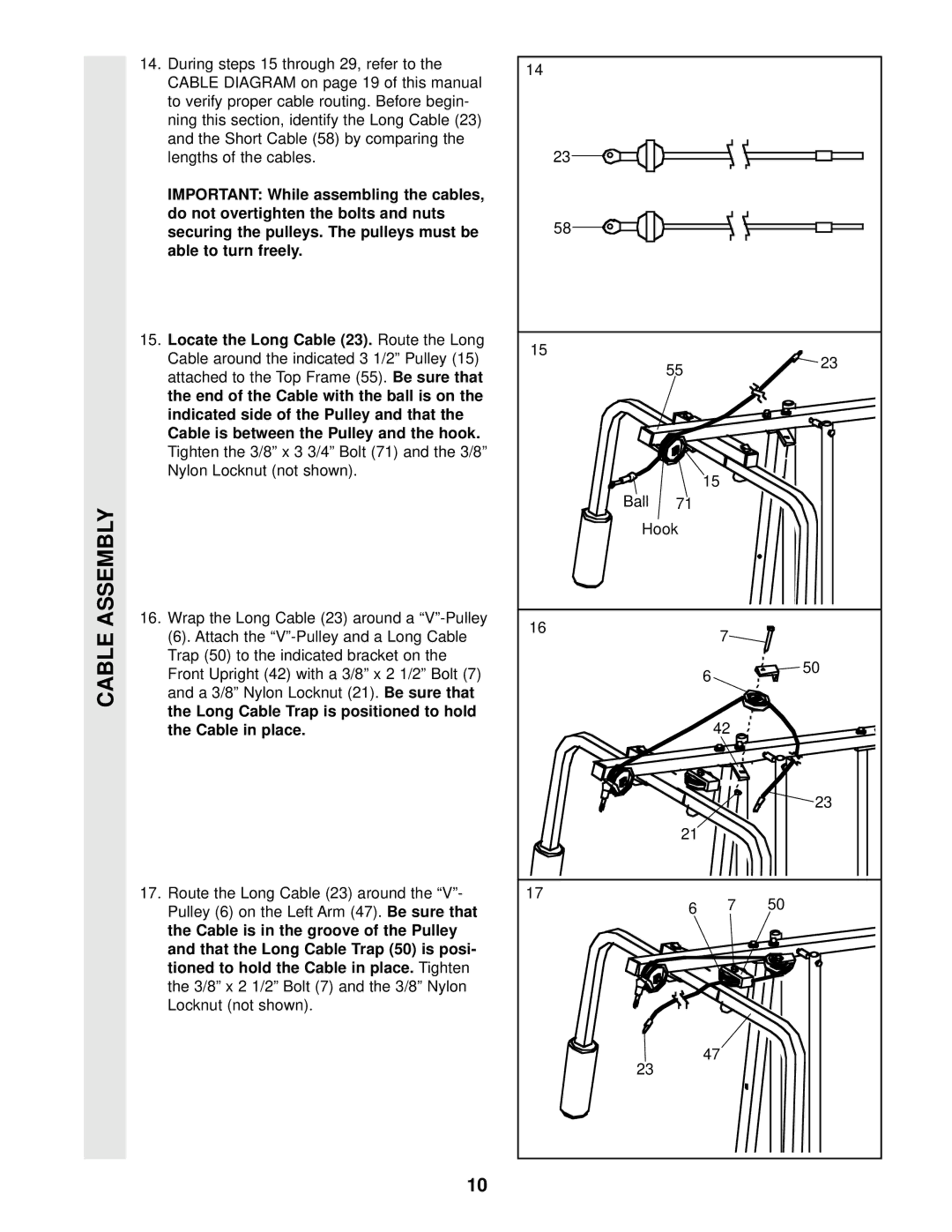
14.During steps 15 through 29, refer to the CABLE DIAGRAM on page 19 of this manual
to verify proper cable routing. Before begin- ning this section, identify the Long Cable (23) and the Short Cable (58) by comparing the lengths of the cables.
IMPORTANT: While assembling the cables, do not overtighten the bolts and nuts securing the pulleys. The pulleys must be able to turn freely.
15. Locate the Long Cable (23). | Route the Long |
Cable around the indicated 3 1/2” Pulley (15) | |
attached to the Top Frame (55). | Be sure that |
the end of the Cable with the ball is on the indicated side of the Pulley and that the Cable is between the Pulley and the hook.
Tighten the 3/8” x 3 3/4” Bolt (71) and the 3/8” Nylon Locknut (not shown).
16.Wrap the Long Cable (23) around a
(6). Attach the
Front Upright (42) with a 3/8” x 2 1/2” Bolt (7)
and a 3/8” Nylon Locknut (21). | Be sure that |
the Long Cable Trap is positioned to hold |
|
the Cable in place. |
|
17. Route the Long Cable (23) around the “V”-
Pulley (6) on the Left Arm (47). | Be sure that |
the Cable is in the groove of the Pulley | |
and that the Long Cable Trap (50) is posi- | |
tioned to hold the Cable in place. | Tighten |
the 3/8” x 2 1/2” Bolt (7) and the 3/8” Nylon Locknut (not shown).
14
23
58
15
55 | 23 |
|
15
Ball 71
Hook
16 |
| 7 |
|
| |
| 6 | 50 |
|
| |
|
| 42 |
23
21
17
6 7 50
47
23
10