Mounting Hardware
Inspect the bay to see whether it is a
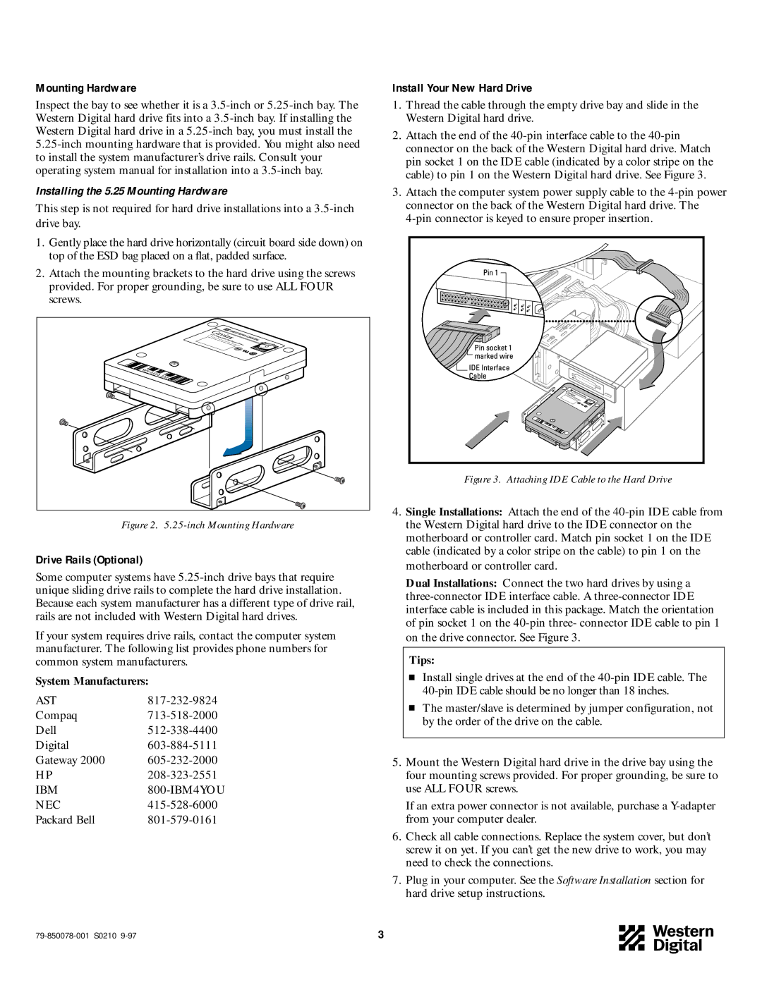
Installing the 5.25 Mounting Hardware
This step is not required for hard drive installations into a
1.Gently place the hard drive horizontally (circuit board side down) on top of the ESD bag placed on a flat, padded surface.
2.Attach the mounting brackets to the hard drive using the screws provided. For proper grounding, be sure to use ALL FOUR screws.
Figure 2. 5.25-inch Mounting Hardware
Drive Rails (Optional)
Some computer systems have
If your system requires drive rails, contact the computer system manufacturer. The following list provides phone numbers for common system manufacturers.
System Manufacturers:
AST | |
Compaq | |
Dell | |
Digital | |
Gateway 2000 | |
HP | |
IBM | |
NEC | |
Packard Bell |
Install Your New Hard Drive
1.Thread the cable through the empty drive bay and slide in the Western Digital hard drive.
2.Attach the end of the
3.Attach the computer system power supply cable to the
Figure 3. Attaching IDE Cable to the Hard Drive
4.Single Installations: Attach the end of the
Dual Installations: Connect the two hard drives by using a
Tips:
Install single drives at the end of the
The master/slave is determined by jumper configuration, not by the order of the drive on the cable.
5.Mount the Western Digital hard drive in the drive bay using the four mounting screws provided. For proper grounding, be sure to use ALL FOUR screws.
If an extra power connector is not available, purchase a
6.Check all cable connections. Replace the system cover, but don’t screw it on yet. If you can’t get the new drive to work, you may need to check the connections.
7.Plug in your computer. See the Software Installation section for hard drive setup instructions.
3 |