The appearance of a properly adjusted gas flame is one having an inner cone of
NOTE: On LP gas a slight yellow tip will be visable on top burner flames, but will not affect burner performance.
b. Oven burners
All burners are lighted by electronic ignitors. DO NOT attempt to insert any object into the openings of the pro- tective shield surrounding the ignitor coil. Do not at- tempt to clean this area. Damage may be caused to ignitor.
BURNER \
ELECTRONIC
FIG. 12
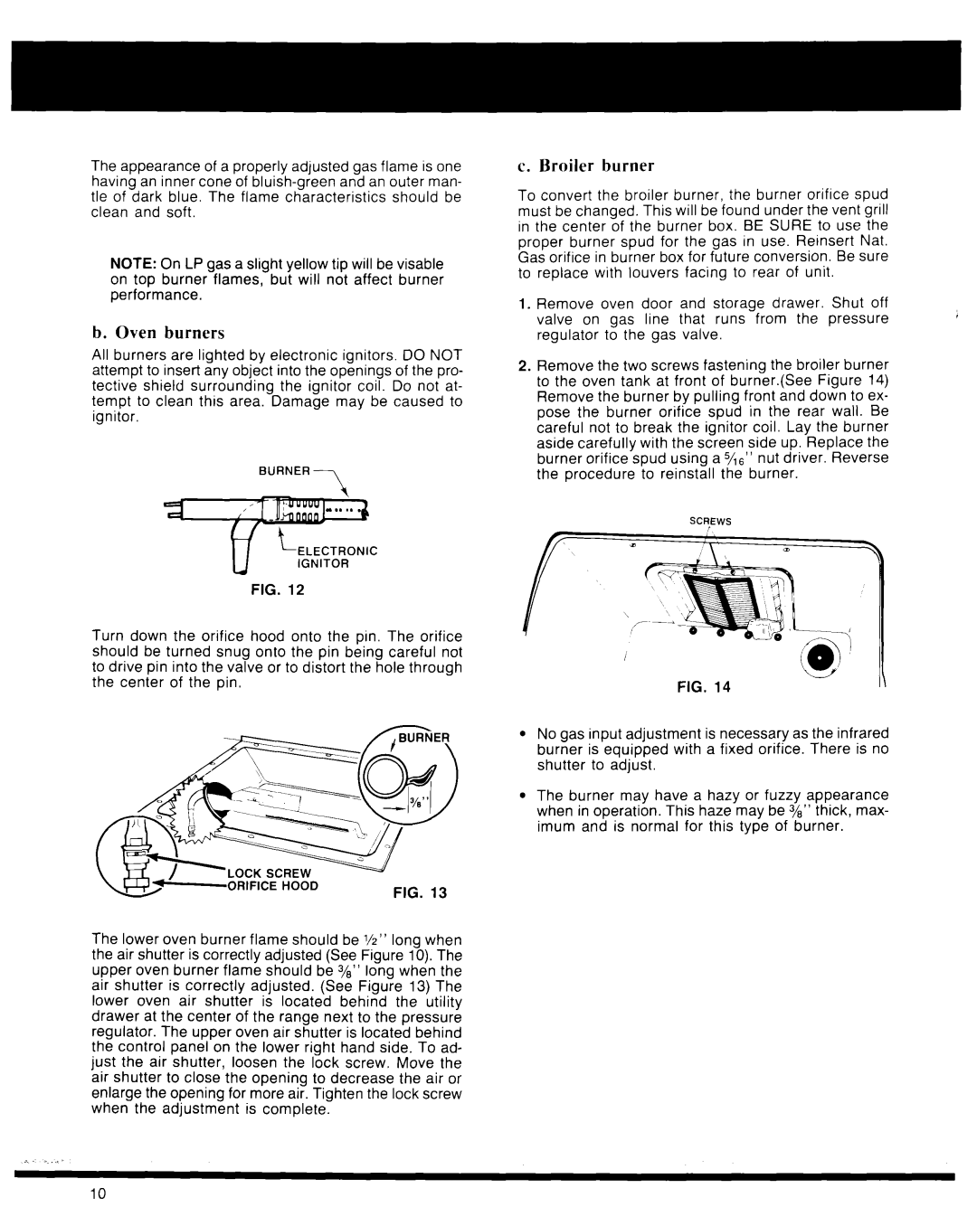
Turn down the orifice hood onto the pin. The orifice should be turned snug onto the pin being careful not to drive pin into the valve or to distort the hole through the center of the pin.
LOCK SCREW |
|
ORIFICE HOOD | FIG. 13 |
|
The lower oven burner flame should be l/z” long when the air shutter is correctly adjusted (See Figure 10). The upper oven burner flame should be 3/e” long when the air shutter is correctly adjusted. (See Figure 13) The lower oven air shutter is located behind the utility drawer at the center of the range next to the pressure regulator. The upper oven air shutter is located behind the control panel on the lower right hand side. To ad- just the air shutter, loosen the lock screw. Move the air shutter to close the opening to decrease the air or enlarge the opening for more air. Tighten the lock screw when the adjustment is complete.
c. Broiler burner
To convert the broiler burner, the burner orifice spud must be changed. This will be found under the vent grill in the center of the burner box. BE SURE to use the proper burner spud for the gas in use. Reinsert Nat. Gas orifice in burner box for future conversion. Be sure to replace with louvers facing to rear of unit.
1.Remove oven door and storage drawer. Shut off valve on gas line that runs from the pressure regulator to the gas valve.
2.Remove the two screws fastening the broiler burner to the oven tank at front of burner.(See Figure 14) Remove the burner by pulling front and down to ex- pose the burner orifice spud in the rear wall. Be careful not to break the ignitor coil. Lay the burner aside carefully with the screen side up. Replace the burner orifice spud using a5/16” nut driver. Reverse the procedure to reinstall the burner.
SCTEWS
lNo gas input adjustment is necessary as the infrared burner is equipped with a fixed orifice. There is no shutter to adjust.
lThe burner may have a hazy or fuzzy appearance when in operation. This haze may be 3/e” thick, max- imum and is normal for this type of burner.
10