Anti-Tip
Bracket
Installation
Imons
Important Safety Warning
To reduce the risk of tipping of the range. the range must be secured to the Hoor by a properly installed
NOTE: If the range is ever moved to a different location. the
Anti-Tip Bracket Installation Instructions
Tools Required:
i/~~,”Nutdriver or Flat Head Screwdriver Adjustable Wrench
Electric Drill & ‘/lb” Dia. Drill Bit
‘/lb” Dia. Masonry Drill Bit (if installing in concrete)
Brachet attachesto the floor at the back of the range to hold both rear leg levelers. When fastening to the floor, be sure that screws do not penetrate electrical u iring or plumbing. The screw\ provided will work in either wood
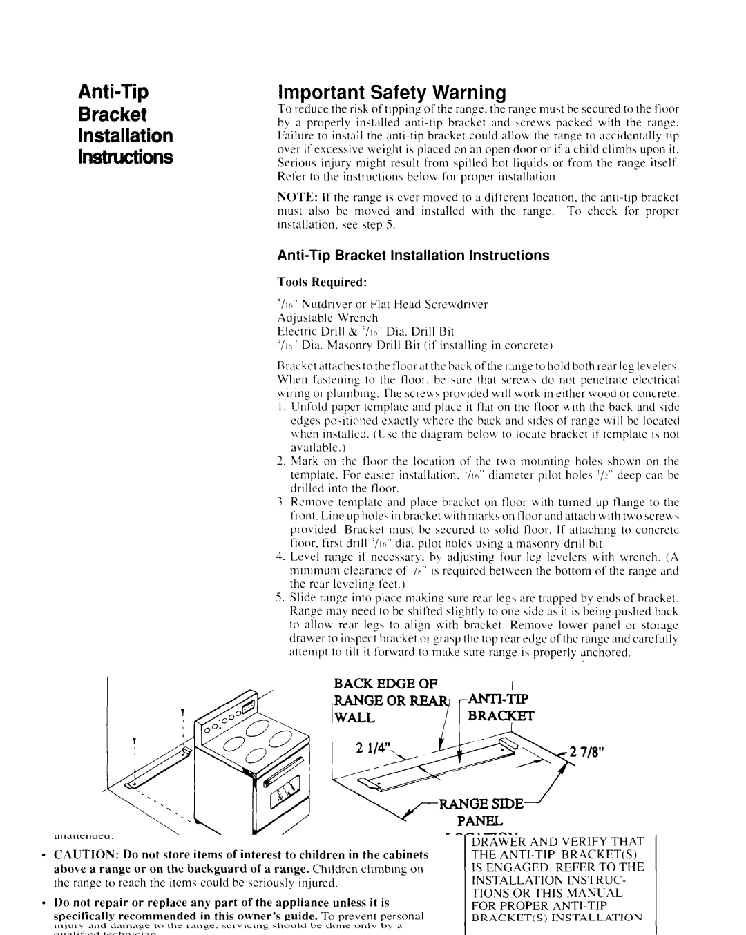
I. Unfold paper template and place it flat on the floor with the back and jidc edges positioned exactly M,herethe back and \ides of range will be located when installed. (LI\c the diagram belou, to locate bracket if template is not available.)
2.Mark on the floor the location of the two mounting holes shown on the template. For easier installation. ‘/Ic,” diameter pilot holes ‘/?‘Ideep can be drilled into the tloor.
3.Remove template and place brnckct on floor with turned up flange to the front. Line up holes in bracket ulith marks on floor and attach with two screw\ provided. Bracket must be secured to solid
4.Level range if necessary. by adJusting four leg levelers with wrench. (A minimum clearance of ‘ix” is required between the bottom of the range and the rear leveling feet.)
5.Slide range into place making sure rear leg\ are trapped by ends of bracket. Range may need to be shifted slightly to one side as it is being pushed back to allow rear legs to align with bracket. Remove lower pane1 or storage drawer to inspect bracket or grasp the top rear edge of the range and carefull! attempt to tilt it forward to make sure range i\ properly anchored.
BACK EDGE OF
RANGE OR
WALLBRACI$ET
LOCATION
SLIDE
BACK
26