Extension Cords
Use proper extension cords. Make sure the cord rating is suitable for the amperage of the machine’s motor. An undersized cord will cause a drop in line voltage resulting in loss of power and overheating.
Use the chart in Figure 9 as a general guide in choosing the correct size cord. The smaller the gauge number, the heavier the cord.
Adjustments
Tilting the Belt Table
The belt table tilts from zero (horizontal) down to 45°.
1.Loosen the handle and adjust the table into desired position.
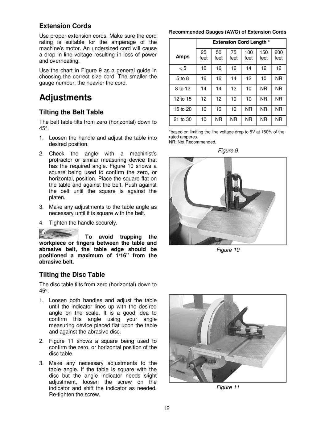
2.Check the angle with a machinist’s protractor or similar measuring device that has the required angle. Figure 10 shows a square being used to confirm the zero, or horizontal, position. Place the square flat on the table and against the belt. Push against the belt until the square is against the platen.
3.Make any adjustments to the table angle as necessary until it is square with the belt.
4.Tighten the handle securely.
![]() To avoid trapping the workpiece or fingers between the table and abrasive belt, the table edge should be positioned a maximum of 1/16” from the abrasive belt.
To avoid trapping the workpiece or fingers between the table and abrasive belt, the table edge should be positioned a maximum of 1/16” from the abrasive belt.
Recommended Gauges (AWG) of Extension Cords
|
| Extension Cord Length * |
| |||
|
|
|
|
|
|
|
Amps | 25 | 50 | 75 | 100 | 150 | 200 |
feet | feet | feet | feet | feet | feet | |
|
|
|
|
|
|
|
< 5 | 16 | 16 | 16 | 14 | 12 | 12 |
|
|
|
|
|
|
|
5 to 8 | 16 | 16 | 14 | 12 | 10 | NR |
|
|
|
|
|
|
|
8 to 12 | 14 | 14 | 12 | 10 | NR | NR |
|
|
|
|
|
|
|
12 to 15 | 12 | 12 | 10 | 10 | NR | NR |
|
|
|
|
|
|
|
15 to 20 | 10 | 10 | 10 | NR | NR | NR |
|
|
|
|
|
|
|
21 to 30 | 10 | NR | NR | NR | NR | NR |
|
|
|
|
|
|
|
*based on limiting the line voltage drop to 5V at 150% of the rated amperes.
NR: Not Recommended.
Figure 9
Figure 10
Tilting the Disc Table
The disc table tilts from zero (horizontal) down to 45°.
1.Loosen both handles and adjust the table until the indicator lines up with the desired angle on the scale. It is a good idea to confirm this angle using your angle measuring device placed flat upon the table and against the abrasive disc.
2.Figure 11 shows a square being used to confirm the zero, or horizontal position of the disc table.
3.Make any necessary adjustments to the table angle. If the table is square with the disc but the angle indicator needs slight adjustment, loosen the screw on the indicator and shift the indicator as needed. Re-tighten the screw.
Figure 11
12