2.Place a warning placard or tag on the service panel to prevent accidental electrical shock.
3.When installing the motor power cord into a receptacle, make sure the plug is compatible with the receptacle.
4.When using
5.Install the fuses or reset the breakers. Check operation of the saw.
Controls and Indicators
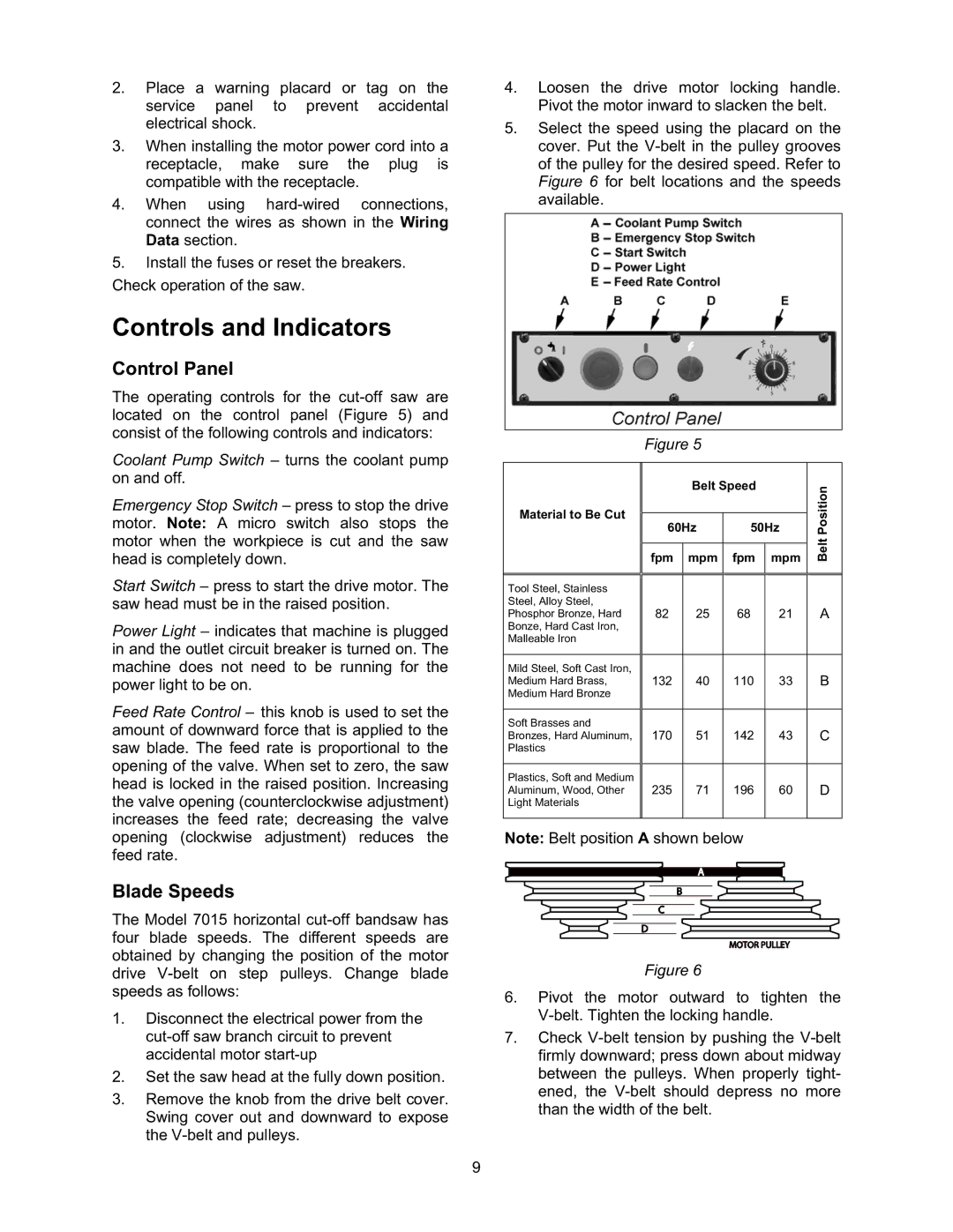
Control Panel
The operating controls for the
Coolant Pump Switch – turns the coolant pump on and off.
Emergency Stop Switch – press to stop the drive motor. Note: A micro switch also stops the motor when the workpiece is cut and the saw head is completely down.
Start Switch – press to start the drive motor. The saw head must be in the raised position.
Power Light – indicates that machine is plugged in and the outlet circuit breaker is turned on. The machine does not need to be running for the power light to be on.
Feed Rate Control – this knob is used to set the amount of downward force that is applied to the saw blade. The feed rate is proportional to the opening of the valve. When set to zero, the saw head is locked in the raised position. Increasing the valve opening (counterclockwise adjustment) increases the feed rate; decreasing the valve opening (clockwise adjustment) reduces the feed rate.
Blade Speeds
The Model 7015 horizontal
1.Disconnect the electrical power from the
2.Set the saw head at the fully down position.
3.Remove the knob from the drive belt cover. Swing cover out and downward to expose the
4.Loosen the drive motor locking handle. Pivot the motor inward to slacken the belt.
5.Select the speed using the placard on the cover. Put the
Figure 5
|
| Belt Speed |
| Position | |
Material to Be Cut | 60Hz | 50Hz | |||
|
|
|
|
| Belt |
| fpm | mpm | fpm | mpm | |
|
|
|
|
|
|
Tool Steel, Stainless |
|
|
|
|
|
Steel, Alloy Steel, |
|
|
|
|
|
Phosphor Bronze, Hard | 82 | 25 | 68 | 21 | A |
Bonze, Hard Cast Iron, |
|
|
|
|
|
Malleable Iron |
|
|
|
|
|
|
|
|
|
|
|
Mild Steel, Soft Cast Iron, |
|
|
|
|
|
Medium Hard Brass, | 132 | 40 | 110 | 33 | B |
Medium Hard Bronze |
|
|
|
|
|
|
|
|
|
|
|
Soft Brasses and |
|
|
|
|
|
Bronzes, Hard Aluminum, | 170 | 51 | 142 | 43 | C |
Plastics |
|
|
|
|
|
|
|
|
|
|
|
Plastics, Soft and Medium |
|
|
|
|
|
Aluminum, Wood, Other | 235 | 71 | 196 | 60 | D |
Light Materials |
|
|
|
|
|
|
|
|
|
|
|
Note: Belt position A shown below
Figure 6
6.Pivot the motor outward to tighten the
7.Check
9