Introduction
This manual includes operating and maintenance instructions for the Wilton
Band Saw Features
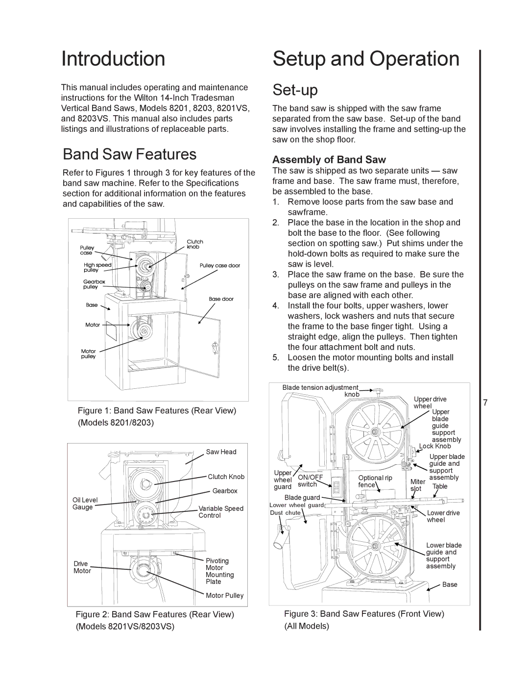
Refer to Figures 1 through 3 for key features of the band saw machine. Refer to the Specifications section for additional information on the features and capabilities of the saw.
Figure 1: Band Saw Features (Rear View) (Models 8201/8203)
Saw Head
Clutch Knob
Gearbox
Oil Level
GaugeVariable Speed
Control
Drive | Pivoting | |
Motor | ||
Motor | ||
Mounting | ||
| ||
| Plate | |
| Motor Pulley |
Figure 2: Band Saw Features (Rear View) (Models 8201VS/8203VS)
Setup and Operation
Set-up
The band saw is shipped with the saw frame separated from the saw base.
Assembly of Band Saw
The saw is shipped as two separate units — saw frame and base. The saw frame must, therefore, be assembled to the base.
1.Remove loose parts from the saw base and sawframe.
2.Place the base in the location in the shop and bolt the base to the floor. (See following section on spotting saw.) Put shims under the
3.Place the saw frame on the base. Be sure the pulleys on the saw frame and pulleys in the base are aligned with each other.
4.Install the four bolts, upper washers, lower washers, lock washers and nuts that secure the frame to the base finger tight. Using a straight edge, align the pulleys. Then tighten the four attachment bolt and nuts.
5.Loosen the motor mounting bolts and install the drive belt(s).
Blade tension adjustment |
|
|
| ||
|
| knob | Upper drive | 7 | |
|
|
| |||
|
|
| wheelUpper | ||
|
|
|
| ||
|
|
|
| blade |
|
|
|
|
| guide |
|
|
|
|
| support |
|
|
|
|
| assembly |
|
|
|
| Lock Knob |
| |
|
|
|
| Upper blade |
|
|
|
|
| guide and |
|
Upper |
|
|
| support |
|
ON/OFF | Optional rip | Miter | assembly |
| |
wheel |
| ||||
guard | switch | fence | slot | Table |
|
Blade guard |
|
|
|
| |
Lower wheel guard |
|
| Lower drive |
| |
Dust chute |
|
|
| ||
|
|
|
| wheel |
|
|
|
|
| Lower blade |
|
|
|
|
| guide and |
|
|
|
|
| support |
|
|
|
|
| assembly |
|
|
|
|
| Base |
|