SUB-FRAME INSTALLATION Cont’d
Sub-Frame Fit-Up (Cont.)
1.Rotate
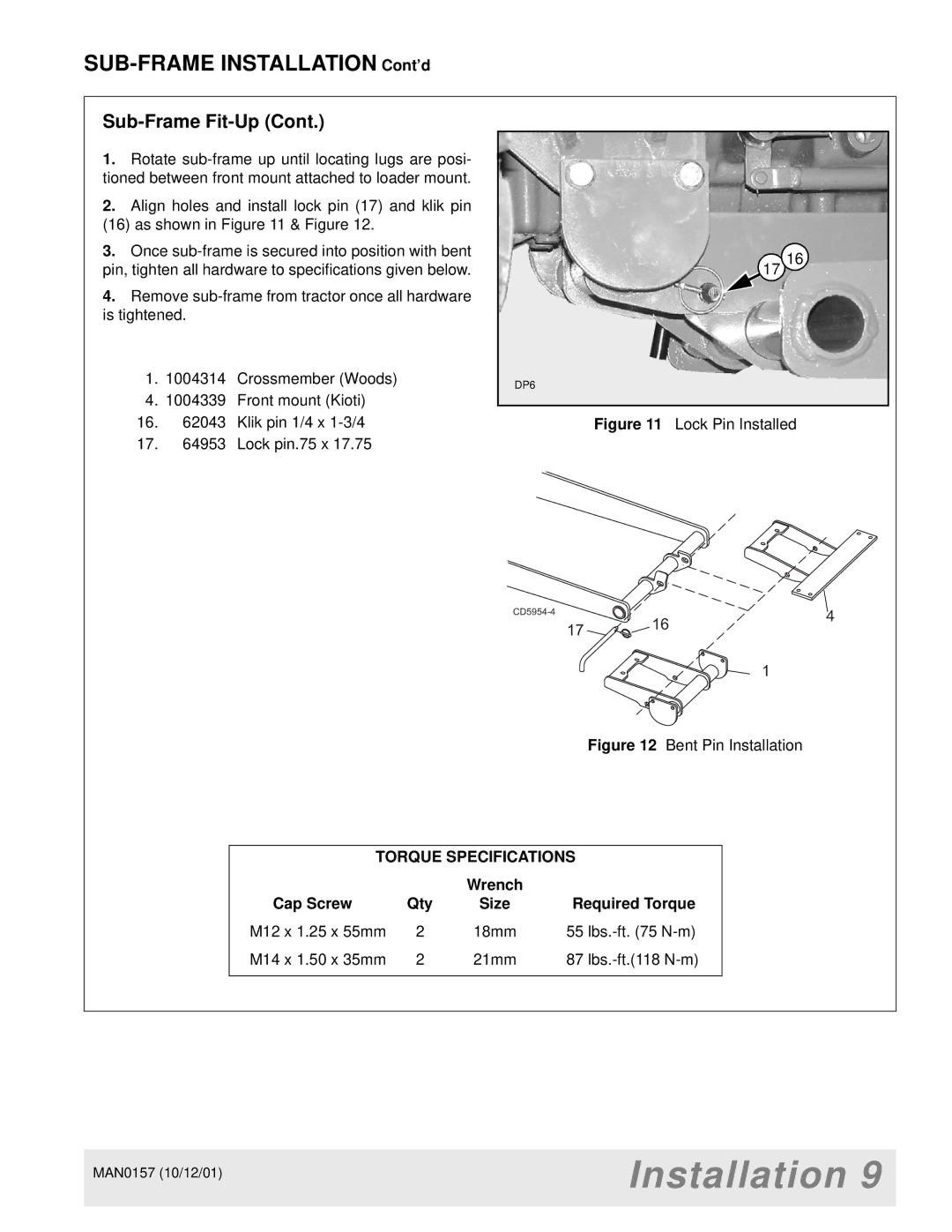
2.Align holes and install lock pin (17) and klik pin (16) as shown in Figure 11 & Figure 12.
3.Once
4.Remove
1.1004314 Crossmember (Woods)
4.1004339 Front mount (Kioti)
16.62043 Klik pin 1/4 x
17.64953 Lock pin.75 x 17.75
17 16
DP6
Figure 11 Lock Pin Installed
|
| 4 | |
| 17 | 16 | |
|
| ||
|
|
|
1
Figure 12 Bent Pin Installation
TORQUE SPECIFICATIONS
|
| Wrench |
|
Cap Screw | Qty | Size | Required Torque |
M12 x 1.25 x 55mm | 2 | 18mm | 55 |
M14 x 1.50 x 35mm | 2 | 21mm | 87 |
MAN0157 (10/12/01) | Installation 9 |
| |
|
|