2 |
#1003179 Hose Kit
(For BH6500/7500 Backhoe & 1009 Loader)
Connect Fittings to Hydraulic Manifold
IMPORTANT
■Incorrect installation can damage the tractor hydraulic system. Read and understand instructions in the tractor manual before connecting.
NOTE: This hose kit contains items that will not be used for installation with the 1009 loader.
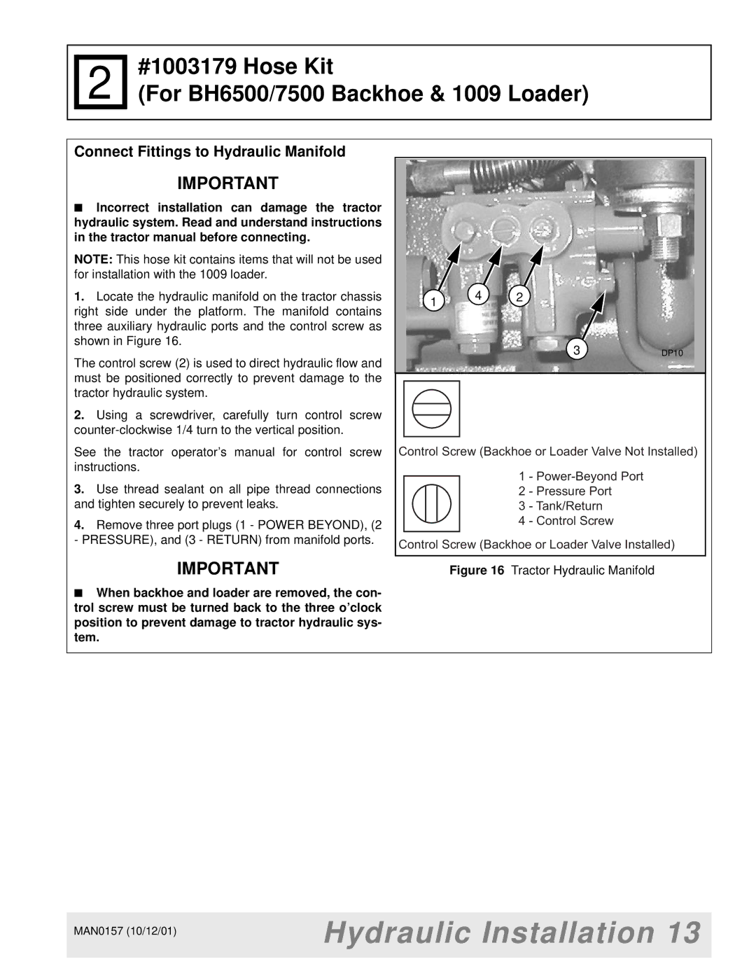
1.Locate the hydraulic manifold on the tractor chassis right side under the platform. The manifold contains three auxiliary hydraulic ports and the control screw as shown in Figure 16.
The control screw (2) is used to direct hydraulic flow and must be positioned correctly to prevent damage to the tractor hydraulic system.
2.Using a screwdriver, carefully turn control screw
See the tractor operator’s manual for control screw instructions.
3.Use thread sealant on all pipe thread connections and tighten securely to prevent leaks.
4.Remove three port plugs (1 - POWER BEYOND), (2 - PRESSURE), and (3 - RETURN) from manifold ports.
IMPORTANT
1 4 2
3DP10
Control Screw (Backhoe or Loader Valve Not Installed)
1 -
2 - Pressure Port
3 - Tank/Return
4 - Control Screw
Control Screw (Backhoe or Loader Valve Installed)
Figure 16 Tractor Hydraulic Manifold
■When backhoe and loader are removed, the con- trol screw must be turned back to the three o’clock position to prevent damage to tractor hydraulic sys- tem.
MAN0157 (10/12/01) | Hydraulic Installation 13 |
| |
|
|