D2057A, D2058A, D2260A Mobile Base Instructions
19.While an assistant lifts up on the back of the machine, slide the rear fixed caster assembly onto the side rails of the front
—If the rear assembly is too narrow or too wide to fit onto the side rails, loosen the hex bolts that secure the corner brackets to the rear rail, adjust the width of the rear fixed caster assembly so it slides into the side rails, then retighten the hex bolts.
Note: It may help to place a 6" 2x4 or 2x6 under the base temporarily if you need to adjust the width of the rear fixed caster assembly (see Figure 27). Remove the block after you finish adjustments.
Note: You may need to tap the assembly to slide it forward onto the side rails and under the machine.
20.Secure each side with (2)
Note: Thread the hex bolts into the rails but do not tighten the lock nuts yet.
21.Tighten the knobs enough to raise the corner brackets, so you can attach the swivel casters in the next step.
22.Mount each of the two swivel casters to a front corner bracket using (4)
23.Tighten all of the lock nuts.
24.Remove the 2x4's from the mobile base.
25.Assembly of the mobile base is complete.
Note: The feet must not touch the floor when moving the mobile base, and the feet must be firmly against the floor in order to operate the machine.
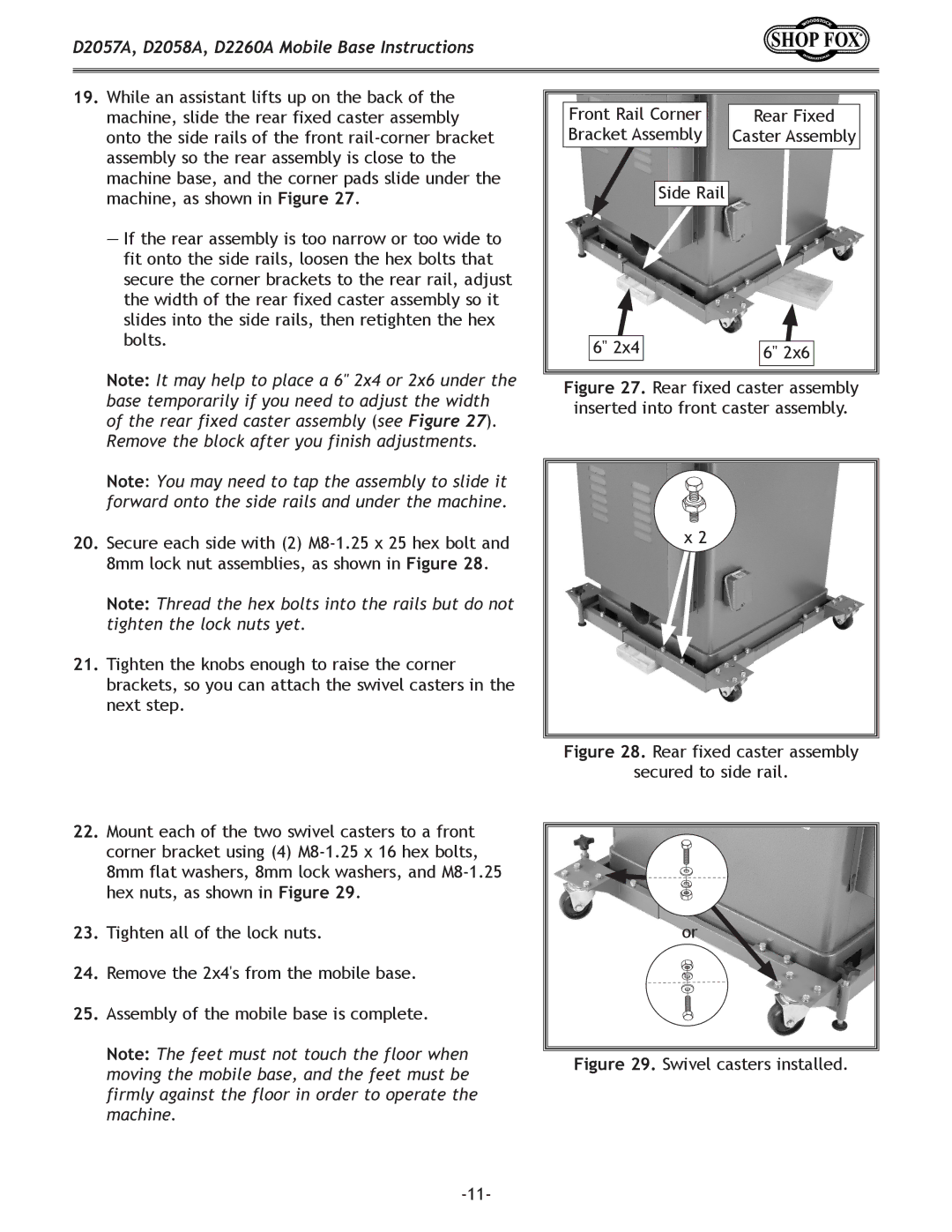
Front Rail Corner | Rear Fixed |
Bracket Assembly | Caster Assembly |
Side Rail |
|
6" 2x4 | 6" 2x6 |
|
Figure 27. Rear fixed caster assembly inserted into front caster assembly.
x 2
Figure 28. Rear fixed caster assembly
secured to side rail.
x![]() 4 or
4 or