D2057A, D2058A, D2260A Mobile Base Instructions
7. Thread (1) 8mm lock nut halfway onto each
8.Secure each end of the rails to the corner brackets with (2)
Each side
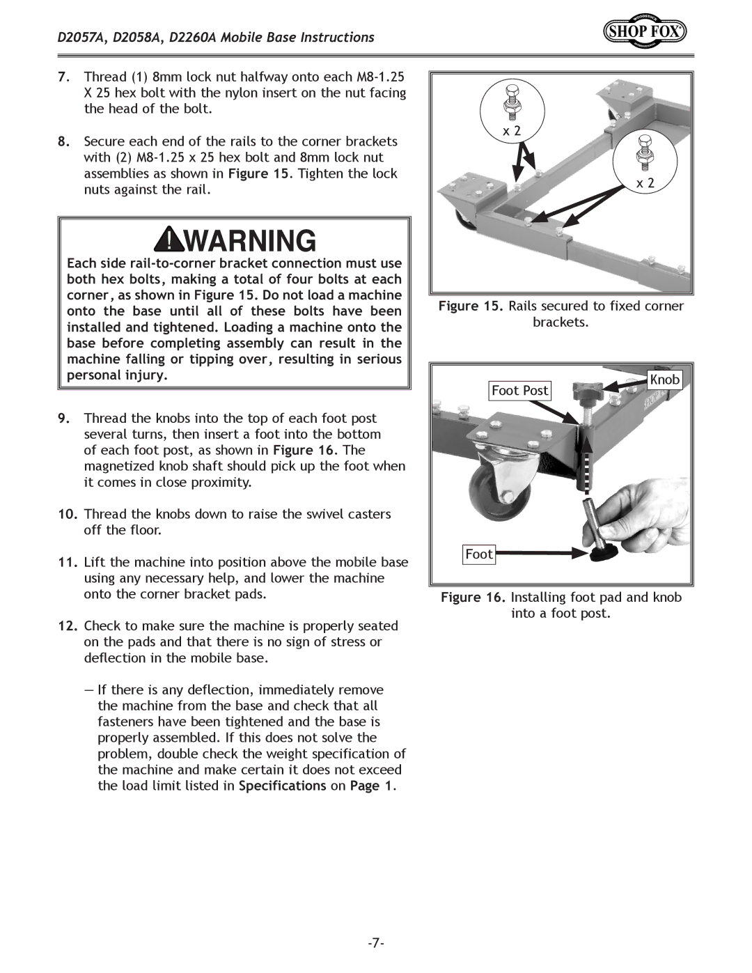
9.Thread the knobs into the top of each foot post several turns, then insert a foot into the bottom of each foot post, as shown in Figure 16. The magnetized knob shaft should pick up the foot when it comes in close proximity.
10.Thread the knobs down to raise the swivel casters off the floor.
11.Lift the machine into position above the mobile base using any necessary help, and lower the machine onto the corner bracket pads.
12.Check to make sure the machine is properly seated on the pads and that there is no sign of stress or deflection in the mobile base.
—If there is any deflection, immediately remove the machine from the base and check that all fasteners have been tightened and the base is properly assembled. If this does not solve the problem, double check the weight specification of the machine and make certain it does not exceed the load limit listed in Specifications on Page 1.
x 2
x 2
Figure 15. Rails secured to fixed corner
brackets.
Foot Post | Knob |
| |
Foot |
|