D2057A, D2058A, D2260A Mobile Base Instructions
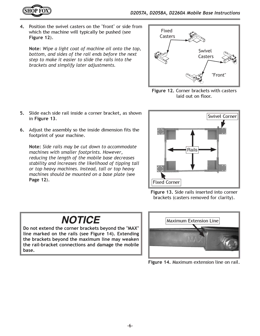
4.Position the swivel casters on the "front" or side from which the machine will typically be pushed (see
Figure 12).
Note: Wipe a light coat of machine oil onto the top, bottom, and sides of the rail ends before the next step to make it easier to slide the rails into the brackets and simplify later adjustments.
Fixed |
Casters |
Swivel |
Casters |
"Front" |
Figure 12. Corner brackets with casters
laid out on floor.
5.Slide each side rail inside a corner bracket, as shown in Figure 13.
6.Adjust the assembly so the inside dimension fits the footprint of your machine.
Note: Side rails may be cut down to accommodate machines with smaller footprints. However, reducing the length of the mobile base decreases stability and increases the likelihood of tipping tall or top heavy machines. Instead, tall or top heavy machines should be mounted on a base plate (see
Page 12).
Swivel Corner |
Rails |
Fixed Corner |
Figure 13. Side rails inserted into corner brackets (casters removed for clarity).
Do not extend the corner brackets beyond the "MAX" line marked on the rails (see Figure 14). Extending the brackets beyond the maximum line may weaken the
Maximum Extension Line