ASSEMBLY
UNPLUG POWER CORD before you do any assem- bly or adjustment tasks! Otherwise, serious per- sonal injury to you or oth- ers may occur!
READ and understand this ![]()
![]()
![]()
![]()
![]() entire instruction manual
entire instruction manual ![]()
![]()
![]()
![]()
![]()
![]() before performing any operations with your machine. Serious personal injury may occur if safety
before performing any operations with your machine. Serious personal injury may occur if safety ![]() and operational informa- tion is not understood and
and operational informa- tion is not understood and
followed.
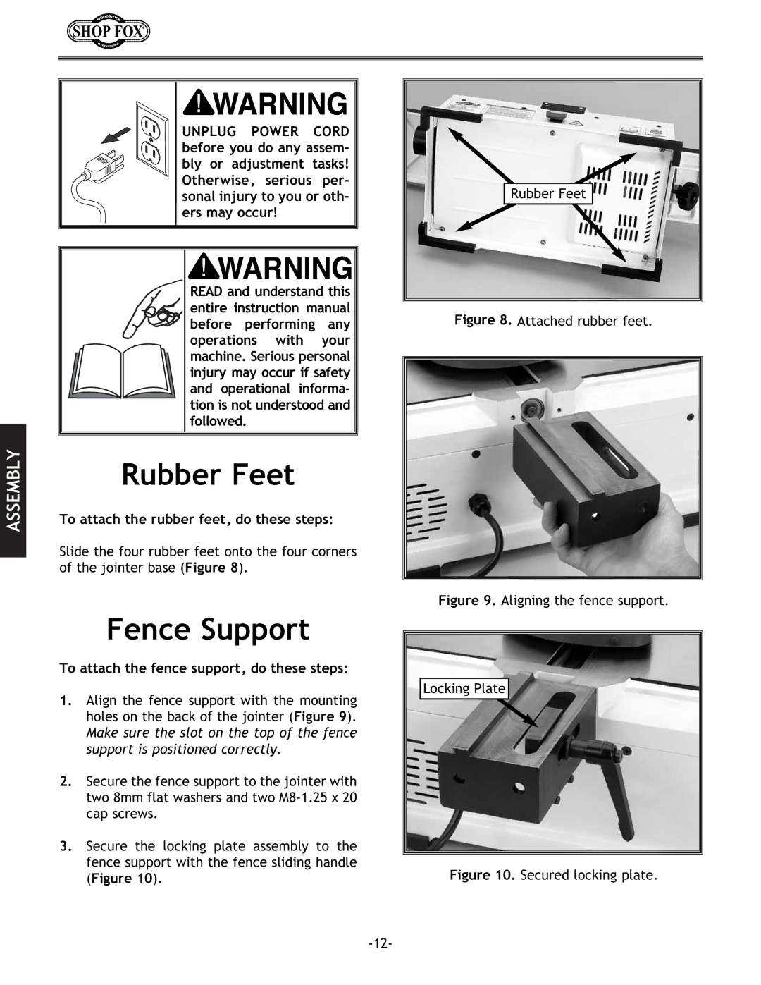
Rubber Feet
To attach the rubber feet, do these steps:
Slide the four rubber feet onto the four corners of the jointer base (Figure 8).
Fence Support
To attach the fence support, do these steps:
1.Align the fence support with the mounting holes on the back of the jointer (Figure 9).
Make sure the slot on the top of the fence support is positioned correctly.
2.Secure the fence support to the jointer with two 8mm flat washers and two
3.Secure the locking plate assembly to the fence support with the fence sliding handle (Figure 10).
Rubber Feet