W1752 Owner's Manual (Mfg. 1/07+)
Adjusting Tool Rest
The tool rest is equipped with a
To position the tool rest base along the bed, do these steps:
1.Loosen the release lever and slide the tool rest base along the bed (Figure 9).
2.
—If the release lever will not lock the tool rest base onto the bed (either too loose or too tight), then loosen or tighten the hex nut (located on the under- side of the tool rest base) in small increments as needed to achieve the proper clamping pressure.
To adjust the tool rest vertically, do these steps:
1.Loosen the lock handles (Figure 9) and adjust the tool rest vertically or swivel it as needed.
2.Tighten the lock handles.
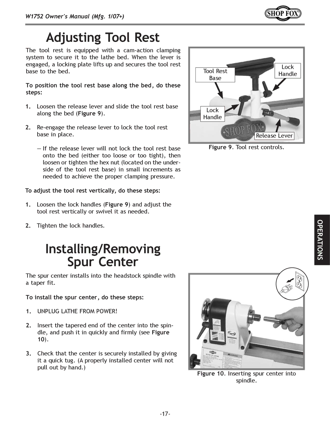
Tool Rest | Lock | |
Handle | ||
Base | ||
| ||
Lock |
| |
Handle |
| |
| Release Lever |
Figure 9. Tool rest controls.
OPERATIONS
Installing/Removing
Spur Center
The spur center installs into the headstock spindle with a taper fit.
To install the spur center, do these steps:
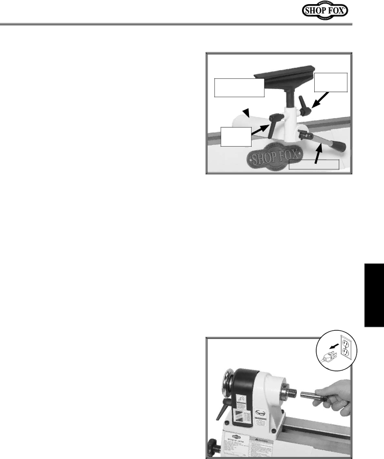
1.Unplug lathe from power!
2.Insert the tapered end of the center into the spin- dle, and push it in quickly and firmly (see Figure 10).
3.Check that the center is securely installed by giving it a quick tug. (A properly installed center will not
pull out by hand.) Figure 10. Inserting spur center into
spindle.