W1752 Owner's Manual (Mfg. 1/07+)
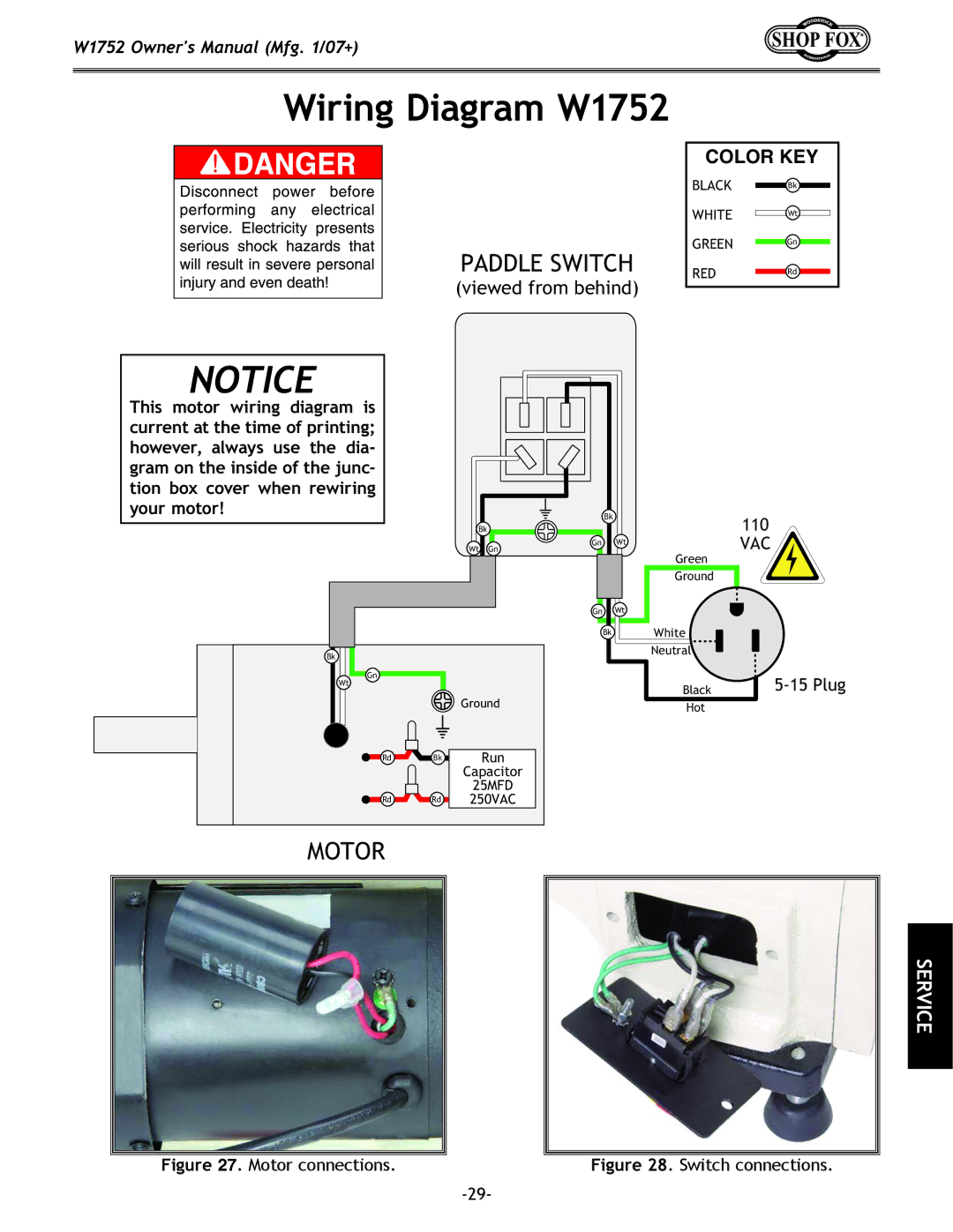
Wiring Diagram W1752
PADDLE SWITCH
(viewed from behind)
COLOR KEY
BLACK Bk
WHITE Wt
GREEN Gn
REDRd
NOTICE
This motor wiring diagram is current at the time of printing; however, always use the dia- gram on the inside of the junc- tion box cover when rewiring your motor!
Bk
Wt Gn
Bk |
|
|
Gn |
|
|
Wt |
|
|
|
| Ground |
Rd | Bk | Run |
|
| Capacitor |
|
| 25MFD |
Rd | Rd | 250VAC |
MOTOR |
|
|
Bk
Gn Wt
Gn Wt
Bk
110
VAC
Green |
Ground |
White
Neutral
| |
Black | |
Hot |
|
SERVICE
Figure 27. Motor connections. |
| Figure 28. Switch connections. |
|
|