ISM4 specifications
The Xantech ISM4 is an innovative multi-zone audio distribution system designed to enhance the listening experience across various environments. This advanced model is particularly suitable for residential and commercial applications, where high-quality audio distribution is crucial.One of the standout features of the ISM4 is its ability to manage up to four separate audio zones. This means users can enjoy different audio sources in different areas simultaneously, catering to diverse preferences and activities. The system supports various audio sources, including streaming services, local media players, and traditional radio, which can all be directed to any zone, providing flexibility and convenience.
The ISM4 utilizes sophisticated digital signal processing (DSP) technology to ensure that audio quality is always at its peak. The DSP allows for customizable audio settings such as equalization, volume adjustment, and audio balance, enabling users to tailor their listening experience to their unique preferences and room characteristics. This level of customization ensures that whether it’s background music in a living room or dynamic sound in a home theater, the audio output is optimized.
Another significant characteristic of the Xantech ISM4 is its user-friendly interface. The system can be controlled via a dedicated app or physical switches, offering versatility in how users interact with their audio setup. The app is compatible with both iOS and Android devices, making it accessible to a wide range of users. Furthermore, the ISM4 can be easily integrated with third-party control systems and home automation solutions, allowing for seamless synchronization with other smart home technology.
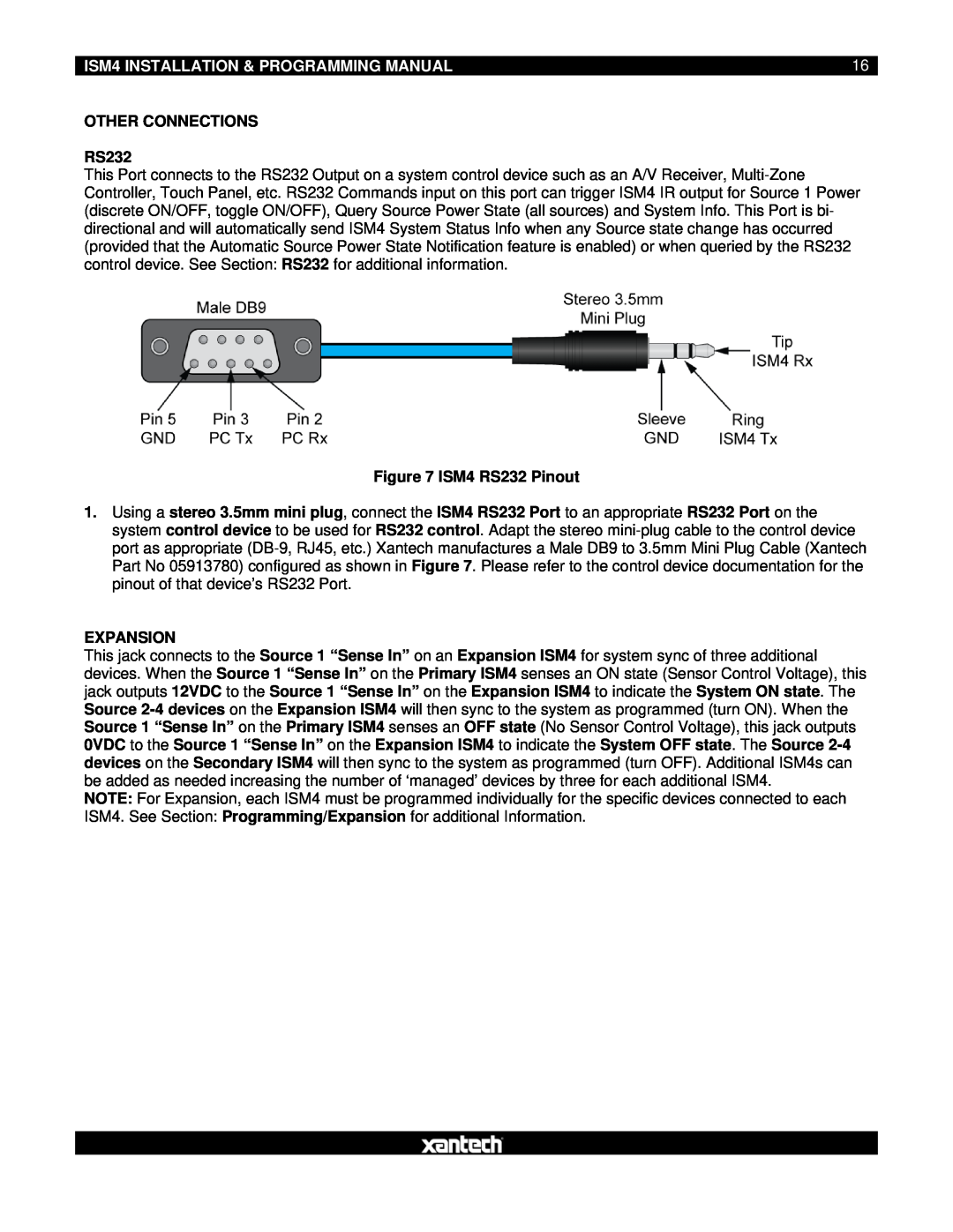
Connectivity is another strong point of the ISM4. It supports various input options, including HDMI, optical, and analog connections, allowing users to connect a variety of audio sources without hassle.
Reliability and durability are ensured through robust build quality, making the ISM4 suitable for long-term use in various environments. With its combination of advanced audio distribution capabilities, user-friendly features, and robust connectivity, the Xantech ISM4 stands out as a leading choice for those looking to elevate their audio experience in both home and commercial settings. Users can expect exceptional sound quality, seamless integration, and the flexibility to enjoy audio the way they want.
