Remote Control Panel
24 V Models
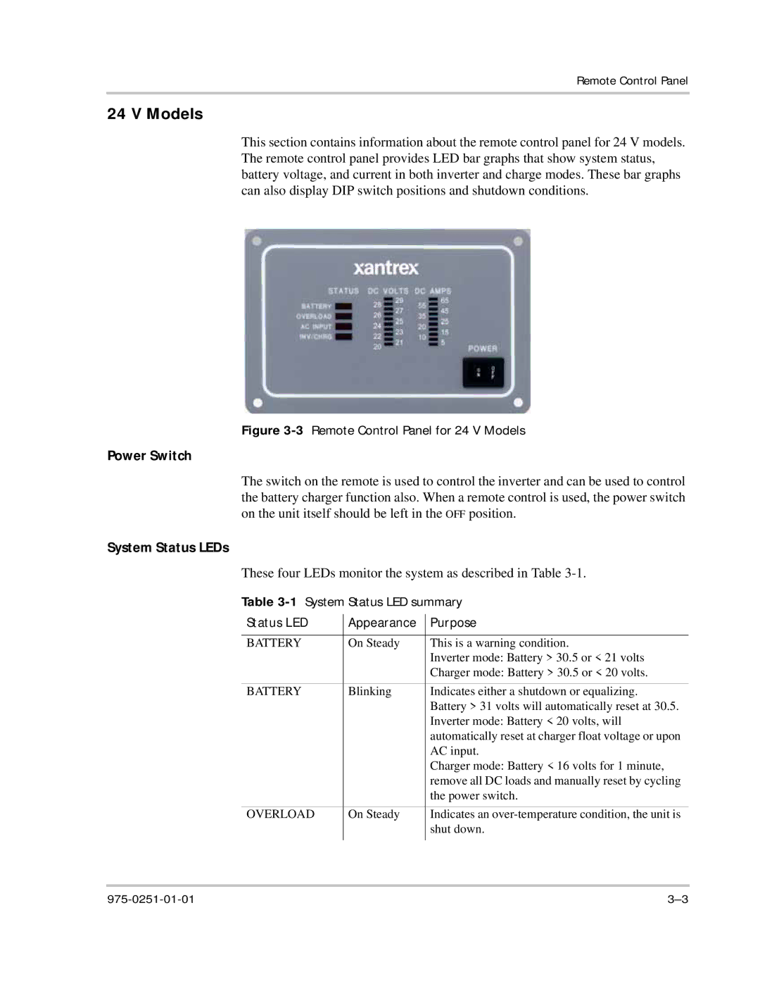
This section contains information about the remote control panel for 24 V models. The remote control panel provides LED bar graphs that show system status, battery voltage, and current in both inverter and charge modes. These bar graphs can also display DIP switch positions and shutdown conditions.
Figure 3-3 Remote Control Panel for 24 V Models
Power Switch
The switch on the remote is used to control the inverter and can be used to control the battery charger function also. When a remote control is used, the power switch on the unit itself should be left in the OFF position.
System Status LEDs
These four LEDs monitor the system as described in Table
Table 3-1 System Status LED summary
Status LED | Appearance | Purpose |
|
|
|
BATTERY | On Steady | This is a warning condition. |
|
| Inverter mode: Battery > 30.5 or < 21 volts |
|
| Charger mode: Battery > 30.5 or < 20 volts. |
BATTERY | Blinking | Indicates either a shutdown or equalizing. |
|
| Battery > 31 volts will automatically reset at 30.5. |
|
| Inverter mode: Battery < 20 volts, will |
|
| automatically reset at charger float voltage or upon |
|
| AC input. |
|
| Charger mode: Battery < 16 volts for 1 minute, |
|
| remove all DC loads and manually reset by cycling |
|
| the power switch. |
OVERLOAD | On Steady | Indicates an |
|
| shut down. |
|
|
|