Operation
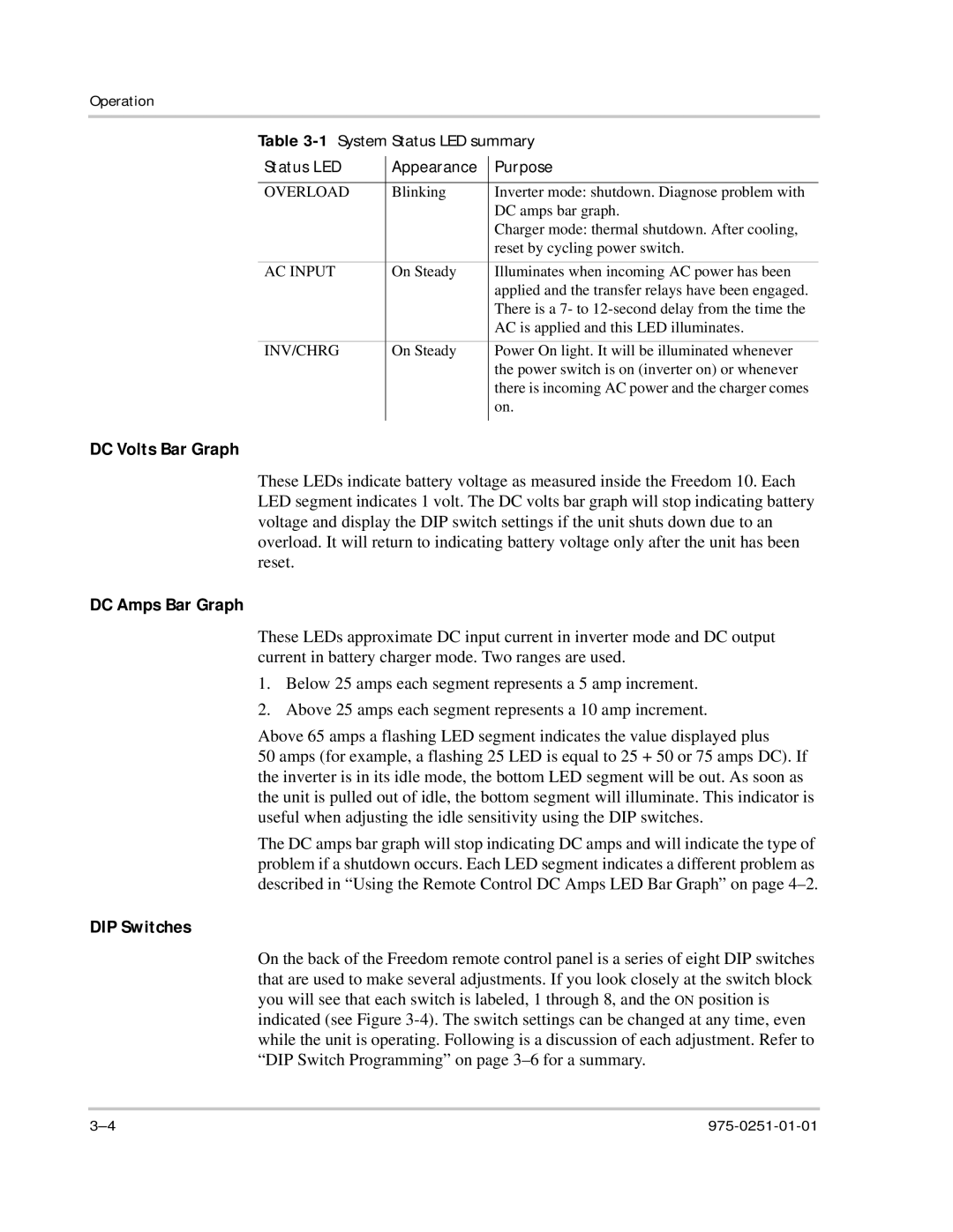
Table 3-1 System Status LED summary
Status LED | Appearance | Purpose |
|
|
|
OVERLOAD | Blinking | Inverter mode: shutdown. Diagnose problem with |
|
| DC amps bar graph. |
|
| Charger mode: thermal shutdown. After cooling, |
|
| reset by cycling power switch. |
AC INPUT | On Steady | Illuminates when incoming AC power has been |
|
| applied and the transfer relays have been engaged. |
|
| There is a 7- to |
|
| AC is applied and this LED illuminates. |
INV/CHRG | On Steady | Power On light. It will be illuminated whenever |
|
| the power switch is on (inverter on) or whenever |
|
| there is incoming AC power and the charger comes |
|
| on. |
|
|
|
DC Volts Bar Graph
These LEDs indicate battery voltage as measured inside the Freedom 10. Each LED segment indicates 1 volt. The DC volts bar graph will stop indicating battery voltage and display the DIP switch settings if the unit shuts down due to an overload. It will return to indicating battery voltage only after the unit has been reset.
DC Amps Bar Graph
These LEDs approximate DC input current in inverter mode and DC output current in battery charger mode. Two ranges are used.
1.Below 25 amps each segment represents a 5 amp increment.
2.Above 25 amps each segment represents a 10 amp increment.
Above 65 amps a flashing LED segment indicates the value displayed plus
50 amps (for example, a flashing 25 LED is equal to 25 + 50 or 75 amps DC). If the inverter is in its idle mode, the bottom LED segment will be out. As soon as the unit is pulled out of idle, the bottom segment will illuminate. This indicator is useful when adjusting the idle sensitivity using the DIP switches.
The DC amps bar graph will stop indicating DC amps and will indicate the type of problem if a shutdown occurs. Each LED segment indicates a different problem as described in “Using the Remote Control DC Amps LED Bar Graph” on page
DIP Switches
On the back of the Freedom remote control panel is a series of eight DIP switches that are used to make several adjustments. If you look closely at the switch block you will see that each switch is labeled, 1 through 8, and the ON position is indicated (see Figure