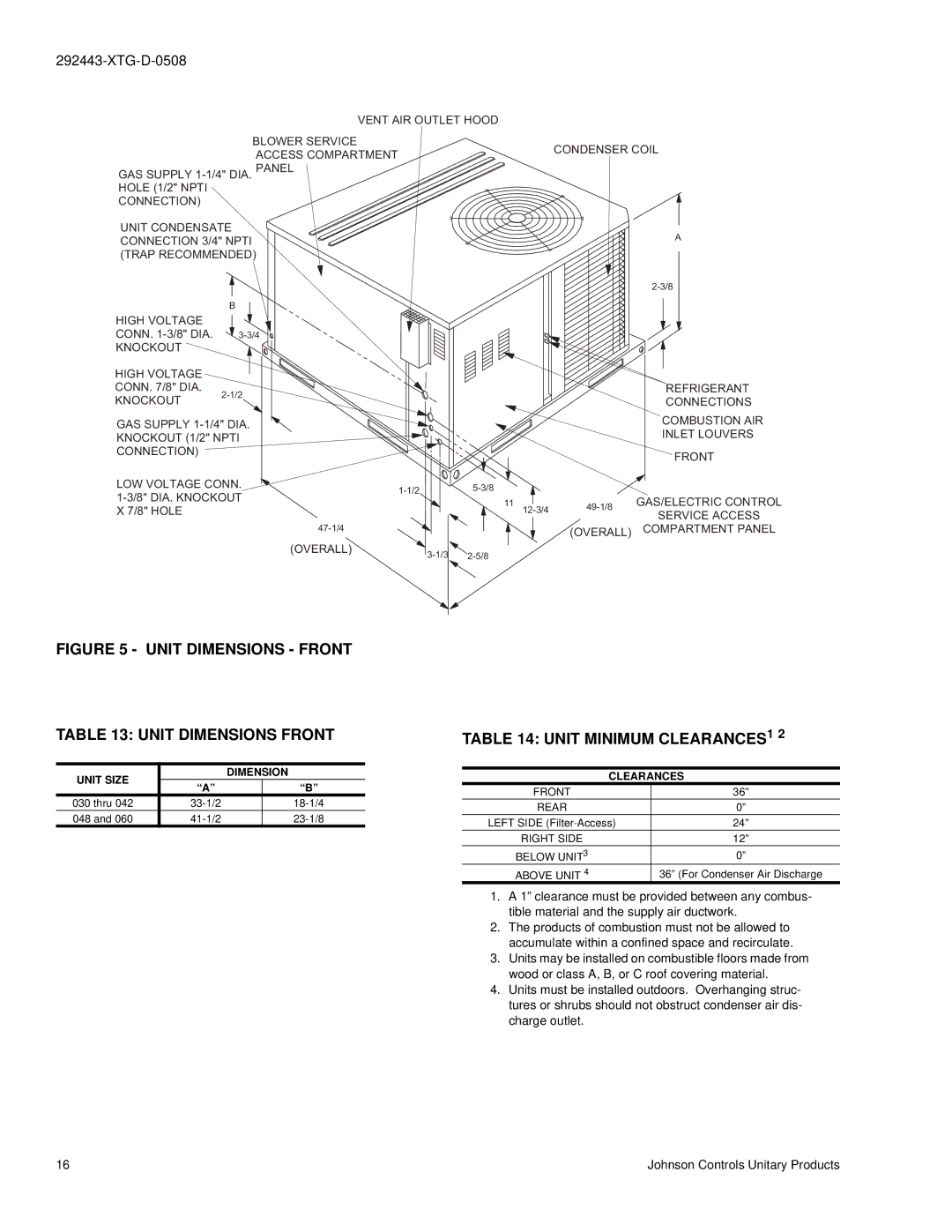
VENT AIR OUTLET HOOD
GAS SUPPLY
BLOWER SERVICE
ACCESS COMPARTMENTCONDENSER COIL PANEL
UNIT CONDENSATE
CONNECTION 3/4" NPTIA (TRAP RECOMMENDED)
B
HIGH VOLTAGE
CONN. ![]()
KNOCKOUT
HIGH VOLTAGE CONN. 7/8" DIA.
REFRIGERANT |
KNOCKOUT
CONNECTIONS |
GAS SUPPLY ![]()
KNOCKOUT (1/2" NPTI
CONNECTION)
LOW VOLTAGE CONN.
(OVERALL)
|
|
|
| COMBUSTION AIR |
|
|
|
| INLET LOUVERS |
|
|
|
| FRONT |
|
| GAS/ELECTRIC CONTROL | ||
| 11 | |||
|
| SERVICE ACCESS | ||
|
|
| ||
|
|
|
| |
|
|
| (OVERALL) | COMPARTMENT PANEL |
|
|
|
FIGURE 5 - UNIT DIMENSIONS - FRONT
TABLE 13: UNIT DIMENSIONS FRONT
UNIT SIZE |
| DIMENSION | |
“A” |
| “B” | |
|
| ||
030 thru 042 |
| ||
048 and 060 |
| ||
TABLE 14: UNIT MINIMUM CLEARANCES1 2
CLEARANCES
FRONT | 36” |
REAR | 0” |
LEFT SIDE | 24” |
RIGHT SIDE | 12” |
BELOW UNIT3 | 0” |
ABOVE UNIT 4 | 36” (For Condenser Air Discharge |
1.A 1” clearance must be provided between any combus- tible material and the supply air ductwork.
2.The products of combustion must not be allowed to accumulate within a confined space and recirculate.
3.Units may be installed on combustible floors made from wood or class A, B, or C roof covering material.
4.Units must be installed outdoors. Overhanging struc- tures or shrubs should not obstruct condenser air dis- charge outlet.
16 | Johnson Controls Unitary Products |