TABLE 10: ADDITIONAL STATIC PRESSURE RESISTANCE
|
|
|
|
|
|
|
| RESISTANCE, IWG |
|
|
|
|
|
| ||
DESCRIPTION |
|
|
|
|
|
|
|
| CFM |
|
|
|
|
|
|
|
| 500 | 600 | 700 | 800 | 900 | 1,000 | 1,100 | 1,200 | 1,300 | 1,400 | 1,500 | 1,600 | 1,700 | 1,800 | 1,900 | 2,000 |
WET EVAPORATOR COIL | .01 | .01 | .01 | .02 | .03 | .04 | .05 | .06 | .07 | .08 | .09 | .09 | - | - | - | - |
ECONOMIZER2 | .00 | .00 | .00 | .01 | .01 | .01 | .01 | .02 | .03 | .04 | .05 | .06 | - | - | - | - |
FILTER FRAME KIT | .01 | .02 | .04 | .06 | .08 | .10 | .13 | .16 | .17 | .18 | .19 | .20 | - | - | - | - |
1.Deduct these resistance values from the available external static pressure shown in Tables 8 and 9.
2.The pressure through the economizer is greater for 100% outdoor air then for 100% return air. If the resistance of the return air duct system is less then 0.25 IWG, the unit will deliver less CFM during full economizer operation.
TABLE 11: ADDITIONAL STATIC PRESSURE RESISTANCE 4 - 5 TON (DNA048 - 060)1
|
|
|
|
|
|
|
| RESISTANCE, IWG |
|
|
|
|
|
| ||
DESCRIPTION |
|
|
|
|
|
|
|
| CFM |
|
|
|
|
|
|
|
| 500 | 600 | 700 | 800 | 900 | 1,000 | 1,100 | 1,200 | 1,300 | 1,400 | 1,500 | 1,600 | 1,700 | 1,800 | 1,900 | 2,000 |
WET EVAPORATOR COIL | - | - | - | - | - | - | - | .03 | .04 | .05 | .06 | .07 | .07 | .08 | .09 | .09 |
ECONOMIZER2 | - | - | - | - | - | - | - | .02 | .02 | .03 | .03 | .04 | .04 | .04 | .05 | .05 |
FILTER FRAME KIT | - | - | - | - | - | - | - | .04 | .05 | .05 | .06 | .07 | .08 | .09 | .10 | .11 |
1.Deduct these resistance values from the available external static pressure shown in Table 8 and 9.
2.The pressure through the economizer is greater for 100% outdoor air then for 100% return air. If the resistance of the return air duct system is less then 0.25 IWG, the unit will deliver less CFM during full economizer operation.
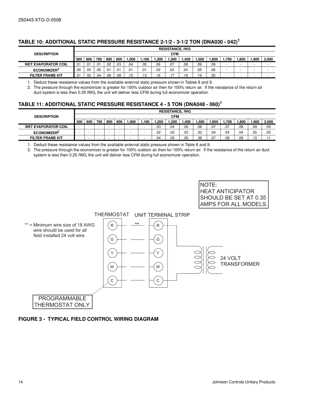
THERMOSTAT | UNIT TERMINAL STRIP | ||
** = Minimum wire size of 18 AWG | R | ** | R |
wire should be used for all |
|
|
|
field installed 24 volt wire. | G |
| G |
|
| ||
| Y |
| Y |
| W |
| W |
| C |
| C |
PROGRAMMABLE
THERMOSTAT ONLY
FIGURE 3 - TYPICAL FIELD CONTROL WIRING DIAGRAM
NOTE:
HEAT ANTICIPATOR SHOULD BE SET AT 0.35 AMPS FOR ALL MODELS.
24VOLT TRANSFORMER
14 | Johnson Controls Unitary Products |